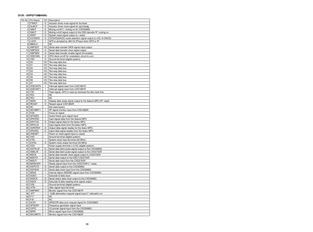
SA-17S1 specifications
The Marantz SA-17S1 is a high-end CD player and SACD player that has earned a reputation for delivering exceptional audio performance and impeccable build quality. Designed for audiophiles, the SA-17S1 combines cutting-edge technology with a thoughtful approach to sound reproduction.One of the standout features of the Marantz SA-17S1 is its advanced digital-to-analog converter (DAC). Utilizing a high-quality DAC, the player ensures that every note and nuance of your favorite music is reproduced with clarity and precision. The choice of DAC technology is pivotal in achieving the level of detail that audiophiles demand, and Marantz has carefully selected components that excel in delivering a rich, natural sound.
The player supports a range of formats, including standard CDs and Super Audio CDs (SACDs), catering to a diverse array of listening preferences. The SA-17S1's ability to handle the higher resolution of SACDs allows listeners to experience music in an entirely new way, capturing the subtleties that are often lost in traditional CD formats.
In addition to its remarkable audio performance, the Marantz SA-17S1 also boasts a robust build quality. The player features a solid chassis that minimizes vibration, ensuring that external disturbances do not compromise sound quality. Additionally, the use of quality materials in the construction enhances both durability and aesthetics, making the SA-17S1 an attractive addition to any high-end audio setup.
The user interface of the SA-17S1 is intuitive and well-designed, allowing for easy navigation through tracks and settings. The remote control offers convenient access to all functionalities, including access to different sound modes and playback options, ensuring that users can tailor their listening experience to their personal preferences.
One of the unique aspects of the SA-17S1 is its high-current output stage, which provides a powerful signal that can drive a range of audio systems with ease. This feature ensures that the player performs well regardless of the connected amplifier or speaker system, making it versatile for various setups.
Overall, the Marantz SA-17S1 is a sophisticated and meticulously crafted audio player that embodies the brand’s commitment to excellence. With its combination of advanced technology, high-performance specifications, and premium build quality, it stands as a notable choice for serious music enthusiasts seeking to elevate their listening experience.
