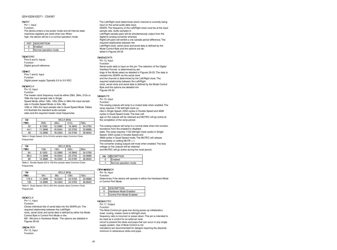
QD41/QD61/QD71 : CS4397

Reset - RST

Pin 1, Input

Function:

The device enters a low power mode and all internal state machines registers are reset when low. When

high, the device will be in a normal operation mode .

RST DESCRIPTION

0Enabled

1Normal operation mode

Digital Ground - DGND

Pins 6 and 9, Inputs

Function:

Digital ground reference.

Digital Power - VD

Pins 7 and 8, Input

Function:

Digital power supply. Typically 5.0 to 3.0 VDC.

Master Clock - MCLK

Pin 10, Input

Function:

The master clock frequency must be either 256x, 384x, 512x or 768x the input sample rate in Single

Speed Mode; either 128x, 192x 256x or 384x the input sample rate in Double Speed Mode; or 64x, 96x

128x or 192x the input sample rate in Quad Speed Mode. Tables 4-6 illustrate the standard audio sample

rates and the required master clock frequencies.

Sample


MCLK (MHz)


Rate (kHz)

256x

384x

512x


768x

32

8.1920

12.2880

16.3840


24.5760

44.1

11.2896

16.9344

22.5792


33.8688

48

12.2880

18.4320

24.5760


36.8640

Table 4. Single Speed (16 to 50 kHz sample rates) Common Clock


Frequencies


Sample


MCLK (MHz)


Rate (kHz)

128x

192x

256x

384x

64

8.1920

12.2880

16.3840

24.5760

88.2

11.2896

16.9344

22.5792

33.8688

96

12.2880

18.4320

24.5760

36.8640

Table 5. Double Speed (50 to 100 kHz sample rates) Common Clock

Frequencies


Sample


MCLK (MHz)


Rate (kHz)

64x

96x

128x

192x

176.4

11.2896

16.9344

22.5792

33.8688

192

12.2880

18.4320

24.5760

36.8640

Table 6. Quad Speed (100 to 200 kHz sample rates) Common Clock Frequencies

Serial Clock - SCLK

Pin 11, Input

Function:

Clocks individual bits of serial data into the SDATA pin. The required relationship between the Left/Right

clock, serial clock and serial data is defined by either the Mode Control Byte in Control Port Mode or the

M0 - M4 pins in Hardware Mode. The options are detailed in Figures 29-33

Left/Right Clock - LRCK

Pin 12, Input

Function:

The Left/Right clock determines which channel is currently being input on the serial audio data input,

SDATA. The frequency of the Left/Right clock must be at the input sample rate. Audio samples in

Left/Right sample pairs will be simultaneously output from the digital-to-analog converter whereas

Right/Left pairs will exhibit a one sample period difference. The required relationship between the

Left/Right clock, serial clock and serial data is defined by the Mode Control Byte and the options are de-

tailed in Figures 29-33

Serial Audio Data - SDATA

Pin 13, Input

Function:

Serial audio data is input on this pin. The selection of the Digital Interface Format is determined by set-

tings of the Mode select as detailed in Figures 29-33. The data is clocked into SDATA via the serial clock

and the channel is determined by the Left/Right clock. The required relationship between the Left/Right

clock, serial clock and serial data is defined by the Mode Control Byte and the options are detailed inin

Figures 29-33

Soft Mute - MUTE

Pin 15, Input

Function:

The analog outputs will ramp to a muted state when enabled. The ramp requires 1152 left/right clock cy-

cles in Single Speed, 2304 cycles in Double Speed and 4608 cycles in Quad Speed mode. The bias volt-

age on the outputs will be retained and MUTEC will go active at the completion of the ramp period.

The analog outputs will ramp to a normal state when this function transitions from the enabled to disabled

state. The ramp requires 1152 left/right clock cycles in Single Speed, 2304 cycles in Double Speed and

4608 cycles in Quad Speed mode. The MUTEC will release immediately on setting MUTE = 1.

The converter analog outputs will mute when enabled. The bias voltage on the outputs will be retained

and MUTEC will go active during the mute period.

Mute DESCRIPTION

0Enabled

1Normal operation mode

Control Port / Hardware Mode Select - C/H

Pin 16, Input

Function:

Determines if the device will operate in either the Hardware Mode or Control Port Mode.

C/H DESCRIPTION

0Hardware Mode Enabled

1Control Port Mode Enabled

Mute Control - MUTEC

Pin 17, Output

Function:

The Mute Control pin goes low during power-up initialization, reset, muting, master clock to left/right clock

frequency ratio is incorrect or power-down. This pin is intended to be used as a control for an external mute

circuit to prevent the clicks and pops that can occur in any single supply system. Use of Mute Control is not

mandatory but recommended for designs requiring the absolute minimum in extraneous clicks and pops.

41

Page 31
Image 31
Marantz SA-17S1 service manual RST Description

SA-17S1 specifications

The Marantz SA-17S1 is a high-end CD player and SACD player that has earned a reputation for delivering exceptional audio performance and impeccable build quality. Designed for audiophiles, the SA-17S1 combines cutting-edge technology with a thoughtful approach to sound reproduction.

One of the standout features of the Marantz SA-17S1 is its advanced digital-to-analog converter (DAC). Utilizing a high-quality DAC, the player ensures that every note and nuance of your favorite music is reproduced with clarity and precision. The choice of DAC technology is pivotal in achieving the level of detail that audiophiles demand, and Marantz has carefully selected components that excel in delivering a rich, natural sound.

The player supports a range of formats, including standard CDs and Super Audio CDs (SACDs), catering to a diverse array of listening preferences. The SA-17S1's ability to handle the higher resolution of SACDs allows listeners to experience music in an entirely new way, capturing the subtleties that are often lost in traditional CD formats.

In addition to its remarkable audio performance, the Marantz SA-17S1 also boasts a robust build quality. The player features a solid chassis that minimizes vibration, ensuring that external disturbances do not compromise sound quality. Additionally, the use of quality materials in the construction enhances both durability and aesthetics, making the SA-17S1 an attractive addition to any high-end audio setup.

The user interface of the SA-17S1 is intuitive and well-designed, allowing for easy navigation through tracks and settings. The remote control offers convenient access to all functionalities, including access to different sound modes and playback options, ensuring that users can tailor their listening experience to their personal preferences.

One of the unique aspects of the SA-17S1 is its high-current output stage, which provides a powerful signal that can drive a range of audio systems with ease. This feature ensures that the player performs well regardless of the connected amplifier or speaker system, making it versatile for various setups.

Overall, the Marantz SA-17S1 is a sophisticated and meticulously crafted audio player that embodies the brand’s commitment to excellence. With its combination of advanced technology, high-performance specifications, and premium build quality, it stands as a notable choice for serious music enthusiasts seeking to elevate their listening experience.