SR7200 specifications
The Marantz SR7200 is a notable receiver that exemplifies high-quality audio performance coupled with advanced technology, making it a staple in home theater systems since its release. Designed for both music aficionados and home theater enthusiasts, the SR7200 offers a versatile array of features that enhance sound quality and user experience.At the core of the SR7200 is a powerful amplification system, providing consumers with 110 watts per channel across seven channels. This ensures that users experience a robust and immersive sound, whether watching movies or listening to music. The receiver supports a wide range of surround sound formats, including Dolby Digital, Dolby Pro Logic II, DTS, and even virtual surround sound options, which allow for a powerful audio experience that fills the room.
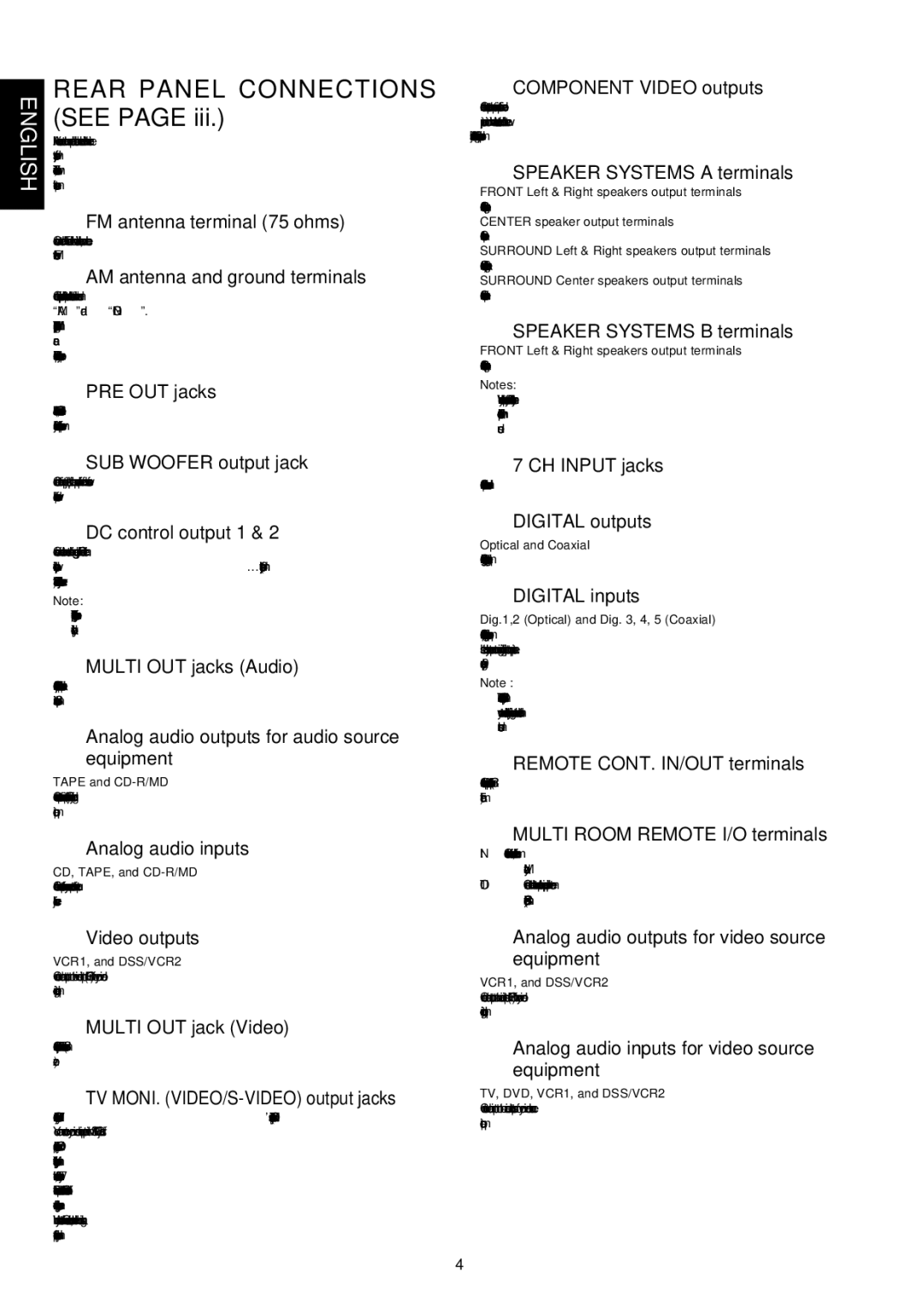
One of the standout features of the Marantz SR7200 is its extensive connectivity options. The receiver is equipped with multiple HDMI inputs, allowing users to connect various sources such as Blu-ray players, gaming consoles, and streaming devices. Additionally, it has composite, component, and optical inputs, making it highly compatible with a multitude of devices. This wide array of inputs ensures that users can enjoy their favorite content without the hassle of switching cables.
The SR7200 also boasts advanced room calibration technology, which helps optimize audio performance according to the unique acoustics of the listening environment. Through the use of microprocessors, the receiver automatically adjusts speaker levels, equalization, and timing to ensure the best possible sound quality, regardless of room layout. This feature is particularly beneficial for novice users who may not have extensive knowledge of audio setup.
In terms of build quality, the Marantz SR7200 is constructed with attention to detail, featuring a solid chassis that is designed to minimize interference and reduce vibrations. The tonal balance is excellent, with crisp highs and deep, rich lows that enhance any audio playback.
Moreover, the receiver is user-friendly, with a nicely designed remote control and an intuitive on-screen setup process, making it accessible for everyone from beginners to seasoned audiophiles.
In summary, the Marantz SR7200 is a feature-rich A/V receiver that combines powerful amplification, multiple connectivity options, advanced audio processing technologies, and user-focused design. It remains a compelling choice for anyone seeking to enhance their home audio experience.