Manuals
/
Maretron
/
Computer Equipment
/
Computer Monitor
Maretron
FPM100 Pressure Transducer Connections, NMEA 2000 Connector Face Views, Page, Revision
Models:
FPM100
1
12
23
23
Download
23 pages
7.43 Kb
9
10
11
12
13
14
15
16
Troubleshooting
Specification
Install
Pin # Signal Name
Warranty
Maintenance
Configuring the FPM100
Features
Page 12
Image 12
Page 11
Page 13
Page 12
Image 12
Page 11
Page 13
Contents
Revision
Page
Revision Copyright 2012 Maretron, LLP All Rights Reserved
Maretron, LLP 9014 N. 23rd Ave #10 Phoenix, AZ
Revision History
FPM100 User’s Manual
Page
Revision
Table of Contents
Table of Figures
Table of Appendices
1.3 Features
1 General
1.1 Introduction
1.2 Firmware Revision
1.4 FPM100 Accessories
1.5 Quick Install
1.6 Theory of Operation
1.6.2 Accuracy of Tank Level Measurement
2 Installation
2.1 Unpacking the Box
Figure 1 - Graph of Transducer Accuracy vs. Tank Depth
2.2 Choosing a Mounting Location
2.3 Mounting the FPM100
2.4 Mounting the Pressure Transducer
2.4.1 Pressure Measurement Applications
2.4.2 Tank Level Measurement Applications
Figure 4 - Fluid Level Measurement with Pressure Transducer
2.5.1 NMEA 2000 Connection
Tank Fitting Ball Valve Pressure Transducer
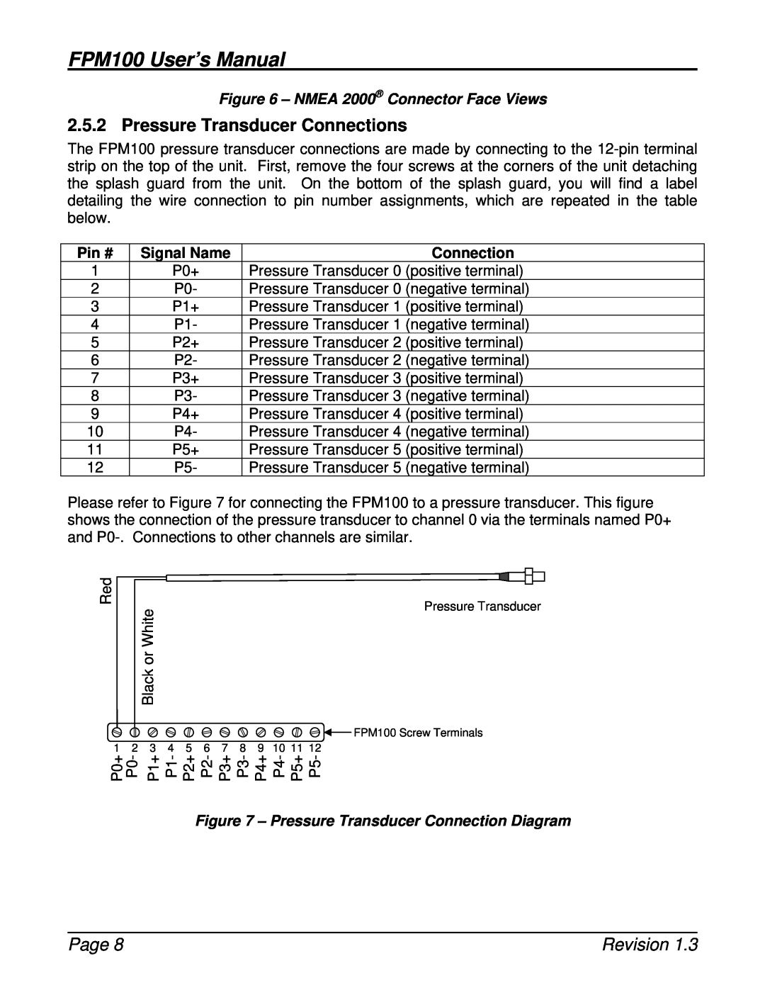
Figure 6 - NMEA 2000 Connector Face Views
Pin # Signal Name
Figure 7 - Pressure Transducer Connection Diagram
2.5.2 Pressure Transducer Connections
3 Configuring the FPM100
3.1 Configuring Channel Mode
3.2 Configuring a Channel in Pressure/Vacuum Mode
3.2.1 Configuring Instance
3.3 Configuring a Channel in Tank Mode
3.2.2 Configuring Label
3.2.3 Configuring Pressure at 4mA
3.2.4 Configuring Pressure at 20mA
3.3.2 Configuring Pressure at 4mA
3.3.3 Configuring Pressure at 20mA
3.3.4 Configuring Tank Capacity
3.3.5 Tank Levels Calibration
3.3.6 Configuring Tank Number
Figure 8 - Empty Tank Depth and Full Tank Depth Parameters
3.3.5.1.3 Fluid Density
3.3.5.2 Custom Calibration
4 Maintenance
3.3.7 Configuring Tank Type
3.3.8 Configuring Data Damping Period
5 Troubleshooting
Symptom
Troubleshooting Procedure
6 Technical Specifications
Figure 9 - Troubleshooting Guide
Specifications Tank Level Mode
Specifications Pressure/Vacuum Mode
7 Technical Support
Electrical
Mechanical
Environmental
8 Installation Template
Figure 10 - Mounting Surface Template
9 Maretron 2 Year Limited Warranty
Warranty Return Procedure
Appendix A - NMEA 2000 Interfacing
FPM100 NMEA 2000 Periodic Data Transmitted PGNs
Appendix A - NMEA 2000 Interfacing
Page A1
Top
Page
Image
Contents