RAA100 User’s Manual
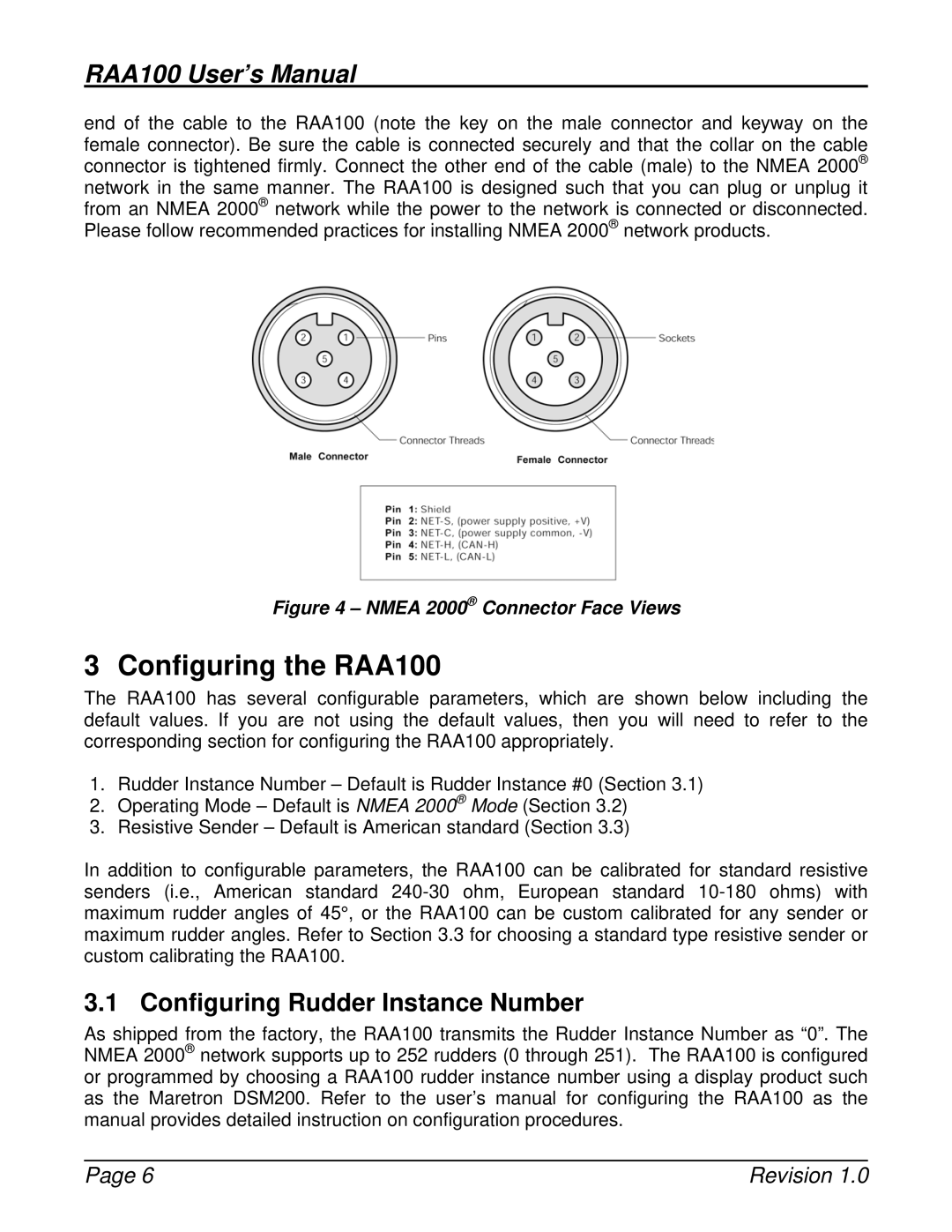
end of the cable to the RAA100 (note the key on the male connector and keyway on the female connector). Be sure the cable is connected securely and that the collar on the cable connector is tightened firmly. Connect the other end of the cable (male) to the NMEA 2000® network in the same manner. The RAA100 is designed such that you can plug or unplug it from an NMEA 2000® network while the power to the network is connected or disconnected. Please follow recommended practices for installing NMEA 2000® network products.
Figure 4 – NMEA 2000® Connector Face Views
3 Configuring the RAA100
The RAA100 has several configurable parameters, which are shown below including the default values. If you are not using the default values, then you will need to refer to the corresponding section for configuring the RAA100 appropriately.
1.Rudder Instance Number – Default is Rudder Instance #0 (Section 3.1)
2.Operating Mode – Default is NMEA 2000® Mode (Section 3.2)
3.Resistive Sender – Default is American standard (Section 3.3)
In addition to configurable parameters, the RAA100 can be calibrated for standard resistive senders (i.e., American standard
3.1 Configuring Rudder Instance Number
As shipped from the factory, the RAA100 transmits the Rudder Instance Number as “0”. The NMEA 2000® network supports up to 252 rudders (0 through 251). The RAA100 is configured or programmed by choosing a RAA100 rudder instance number using a display product such as the Maretron DSM200. Refer to the user’s manual for configuring the RAA100 as the manual provides detailed instruction on configuration procedures.
Page 6 | Revision 1.0 |