Manuals
/
Mark Levinson
/
Home Audio
/
Stereo Amplifier
Mark Levinson
433 trigger in and out connectors, power save mode switch, Mark Levinson
Models:
433
1
18
34
34
Download
34 pages
23.04 Kb
15
16
17
18
19
20
21
22
Troubleshooting
Specification
Install
These fault conditions include
Indicator LED
Dimension
Maintenance
9. ~ac mains connector
Safety
No433 Power Amplifier
Page 18
Image 18
Page 17
Page 19
Page 18
Image 18
Page 17
Page 19
Contents
No433 Power Amplifier
Important Safety Instructions
FCC Notice
Important Safety Instructions
operate the equipment
2005 Harman Specialty Group. All rights reserved
Table of Contents
Unpacking
Product Registration
Installation Considerations
Placement
Ventilation
Mark Levinson
Power Requirements
Warm-up& Break-InPeriod
2. Sleep Mode
Operating States
1. Off
3. Standby
Special Design Features
Massive Power Supply Balanced Design
Extensive Protection
These fault conditions include
Mark Levinson
Front Panel
1. Indicator LED
2. Power Button
3. Standby Button
Mark Levinson
Rear Panel
1. Rear Panel Handles
2. Loudspeaker Binding Posts Outputs
3. Unbalanced Input
5. RS-232Communications Port
Nº433 Power Amplifier
4. Balanced Input
6. Communication Ports
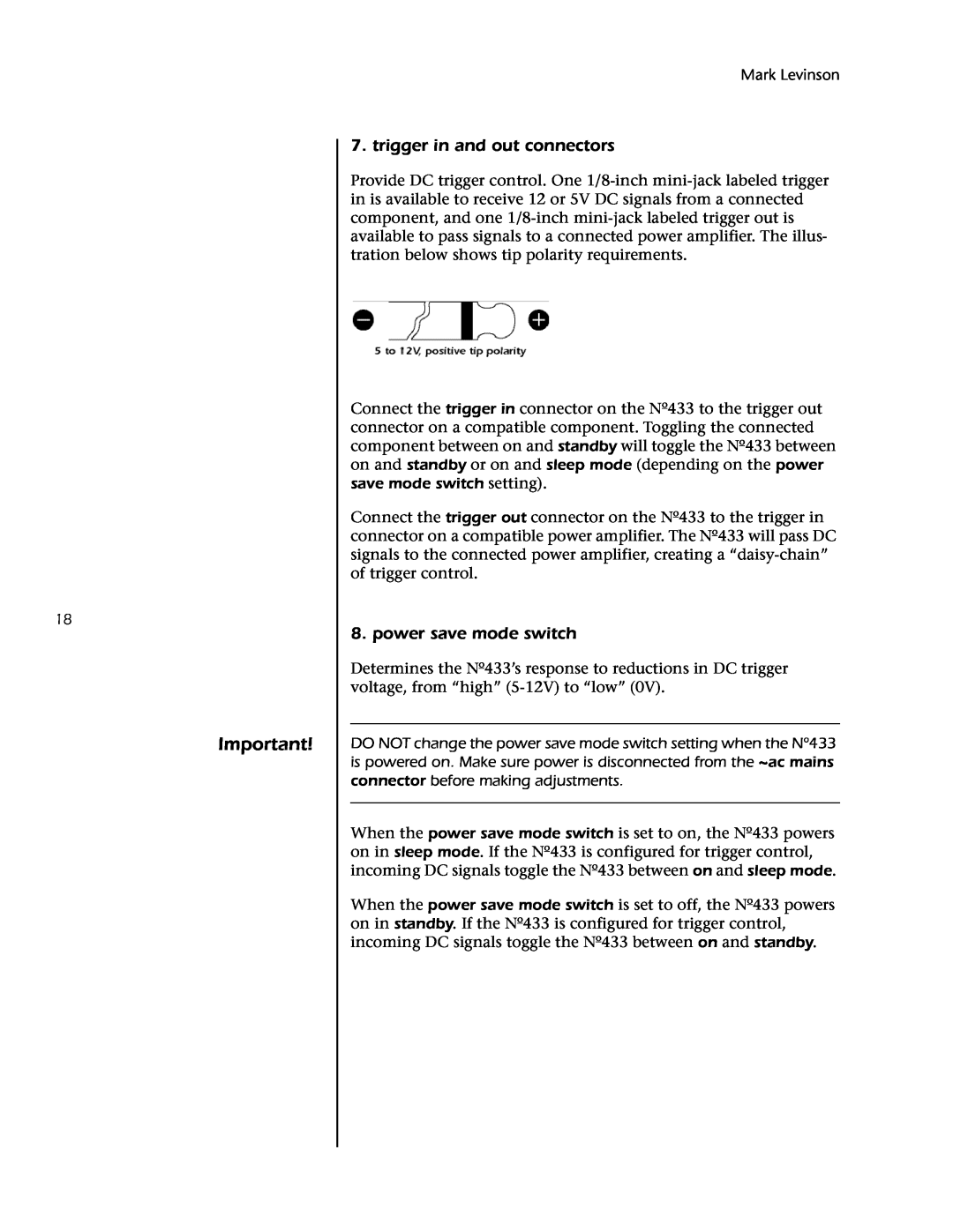
7. trigger in and out connectors
8. power save mode switch
Mark Levinson
Danger
9. ~ac mains connector
Linking
Making Link Connections
communication port specifications for other
Constructing Link Communication Cables
Nº433 Power Amplifier
tation for Link or
Component
Creating a Slave Chain
Mark Levinson
Requirements and Connections
To create a slave chain that includes the Nº433
Nº433 Power Amplifier
Power Amplifier
No40 Media Console
Mark Levinson
Power Amplifier
Link Controls
Nº433 Power Amplifier
Note the following
Troubleshooting
Danger
Nº433 Power Amplifier
8. The amplifier keeps powering off
9. If all else fails
Mark Levinson
Care & Maintenance
Nº433 Power Amplifier
Signal to Noise ratio Input impedance
Specifications
Rated power output Frequency response
Power consumption Mains voltage
Standards to which Conformity is Declared
Declaration of Conformity
Application of Council Directives
Manufacturer
Mark Levinson
Dimensions
standby power
17.75 45.09 cm
Rack-Mounting
Part No. 070-630694 Rev 1 09/05
Top
Page
Image
Contents