CHIMNEY CAP CHASE INSTALLATION
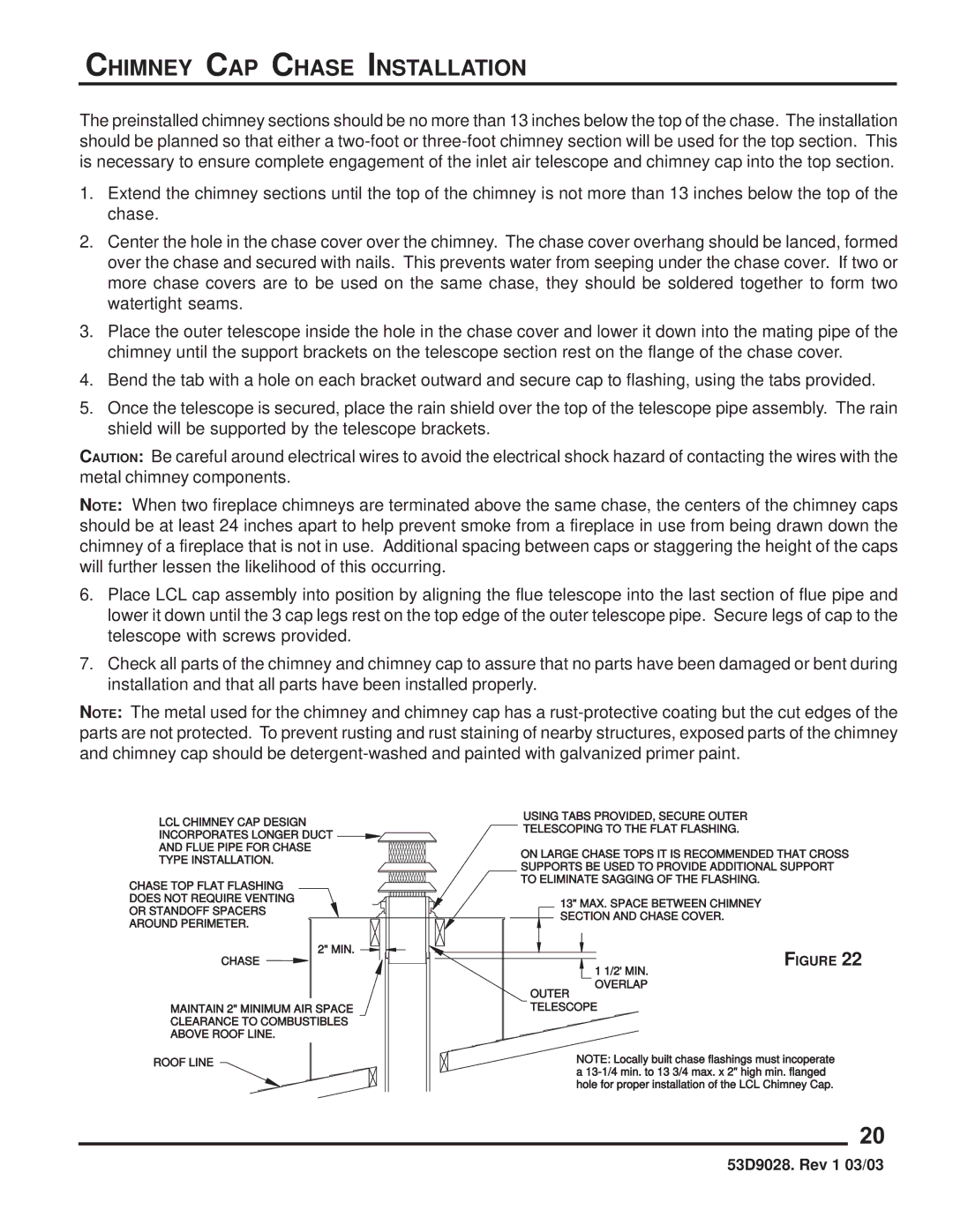
The preinstalled chimney sections should be no more than 13 inches below the top of the chase. The installation should be planned so that either a
1.Extend the chimney sections until the top of the chimney is not more than 13 inches below the top of the chase.
2.Center the hole in the chase cover over the chimney. The chase cover overhang should be lanced, formed over the chase and secured with nails. This prevents water from seeping under the chase cover. If two or more chase covers are to be used on the same chase, they should be soldered together to form two watertight seams.
3.Place the outer telescope inside the hole in the chase cover and lower it down into the mating pipe of the chimney until the support brackets on the telescope section rest on the flange of the chase cover.
4.Bend the tab with a hole on each bracket outward and secure cap to flashing, using the tabs provided.
5.Once the telescope is secured, place the rain shield over the top of the telescope pipe assembly. The rain shield will be supported by the telescope brackets.
CAUTION: Be careful around electrical wires to avoid the electrical shock hazard of contacting the wires with the metal chimney components.
NOTE: When two fireplace chimneys are terminated above the same chase, the centers of the chimney caps should be at least 24 inches apart to help prevent smoke from a fireplace in use from being drawn down the chimney of a fireplace that is not in use. Additional spacing between caps or staggering the height of the caps will further lessen the likelihood of this occurring.
6.Place LCL cap assembly into position by aligning the flue telescope into the last section of flue pipe and lower it down until the 3 cap legs rest on the top edge of the outer telescope pipe. Secure legs of cap to the telescope with screws provided.
7.Check all parts of the chimney and chimney cap to assure that no parts have been damaged or bent during installation and that all parts have been installed properly.
NOTE: The metal used for the chimney and chimney cap has a
LCL CHIMNEY CAP DESIGN
INCORPORATES LONGER DUCT ![]()
AND FLUE PIPE FOR CHASE
TYPE INSTALLATION.
CHASE TOP FLAT FLASHING
DOES NOT REQUIRE VENTING
OR STANDOFF SPACERS
AROUND PERIMETER.
2" MIN. ![]()
![]()
CHASE
MAINTAIN 2" MINIMUM AIR SPACE
CLEARANCE TO COMBUSTIBLES
ABOVE ROOF LINE.
ROOF LINE
USING TABS PROVIDED, SECURE OUTER
TELESCOPING TO THE FLAT FLASHING.
ON LARGE CHASE TOPS IT IS RECOMMENDED THAT CROSS SUPPORTS BE USED TO PROVIDE ADDITIONAL SUPPORT TO ELIMINATE SAGGING OF THE FLASHING.
13" MAX. SPACE BETWEEN CHIMNEY SECTION AND CHASE COVER.
FIGURE 22
1 1/2' MIN.
OVERLAP
OUTER
TELESCOPE
NOTE: Locally built chase flashings must incoperate a
20
53D9028. Rev 1 03/03
