OWNER’S MANUAL

SERVICE

PROCEDURES

Continued

Fan

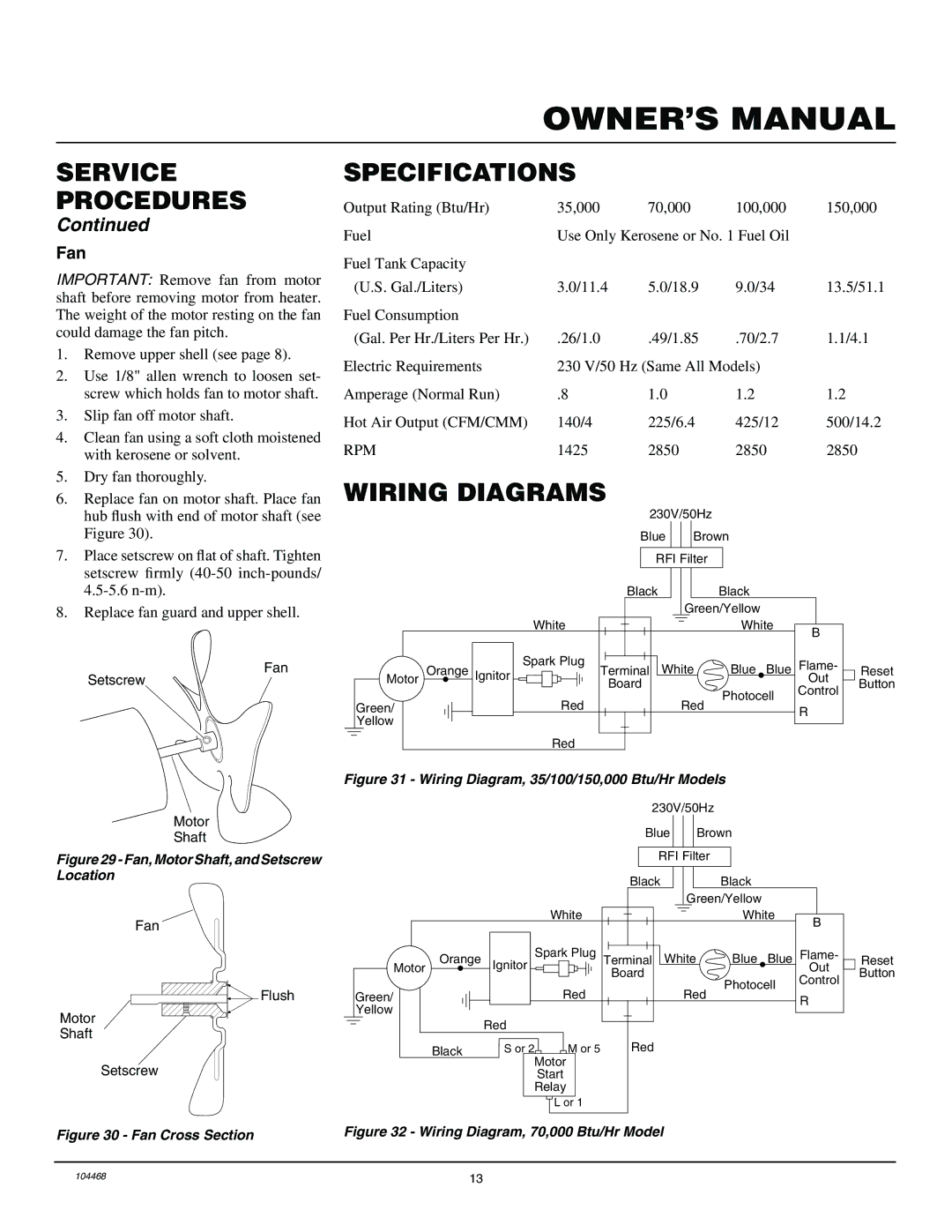
IMPORTANT: Remove fan from motor shaft before removing motor from heater. The weight of the motor resting on the fan could damage the fan pitch.

1.Remove upper shell (see page 8).

2.Use 1/8" allen wrench to loosen set- screw which holds fan to motor shaft.

3.Slip fan off motor shaft.

4.Clean fan using a soft cloth moistened with kerosene or solvent.

5.Dry fan thoroughly.

6.Replace fan on motor shaft. Place fan hub flush with end of motor shaft (see Figure 30).

7.Place setscrew on flat of shaft. Tighten setscrew firmly (40-50 inch-pounds/ 4.5-5.6 n-m).

8.Replace fan guard and upper shell.

Fan

Setscrew

Motor

Shaft

Figure 29 - Fan, Motor Shaft, and Setscrew Location

Fan

SPECIFICATIONS

Output Rating (Btu/Hr)

35,000

70,000

100,000

150,000

Fuel

Use Only Kerosene or No. 1 Fuel Oil


Fuel Tank Capacity


(U.S. Gal./Liters)

3.0/11.4

5.0/18.9

9.0/34

13.5/51.1

Fuel Consumption


(Gal. Per Hr./Liters Per Hr.)

.26/1.0

.49/1.85

.70/2.7

1.1/4.1

Electric Requirements

230 V/50 Hz (Same All Models)


Amperage (Normal Run)

.8

1.0

1.2

1.2

Hot Air Output (CFM/CMM)

140/4

225/6.4

425/12

500/14.2

RPM

1425

2850

2850

2850

WIRING DIAGRAMS

230V/50Hz

Blue Brown

RFI Filter


Black


Black


Green/Yellow


White


White

B


Orange


Spark Plug

White

Blue Blue

Flame-

Reset

Motor

Ignitor

Terminal


Board


Out

Button


Photocell

Control


Green/


Red

Red


R


Yellow


Red


Figure 31 - Wiring Diagram, 35/100/150,000 Btu/Hr Models

230V/50Hz

Blue


Brown


RFI Filter


Black


Black


Green/Yellow


White


White

B


Orange

Spark Plug

Terminal

White

Blue

Blue

Flame-

Reset

Motor

Ignitor

Board


Out

Button


Control

Motor Shaft

Flush


Green/


Red


Red

Photocell


R


Yellow


Red


Red


Black


S or

2


M

or 5


Motor


Setscrew

Figure 30 - Fan Cross Section

Start

Relay

L or 1

Figure 32 - Wiring Diagram, 70,000 Btu/Hr Model

104468

13

Page 13
Image 13
Master Lock B35CEA, B70CEA, B150CEA, B100CEA owner manual Specifications, Wiring Diagrams, Fan

B150CEA, B100CEA, B35CEA, B70CEA specifications

Master Lock is a renowned name in security solutions, offering a wide range of products designed to enhance safety and peace of mind. Among its notable offerings are the B70CEA, B35CEA, B100CEA, and B150CEA padlocks, each tailored for specific applications while ensuring robust protection.

The Master Lock B70CEA is a part of the company's heavy-duty padlock line. This lock features a 1.5-inch (38 mm) wide reinforced metallic body for exceptional strength and durability. Equipped with a boron alloy shackle that stands at 2 inches (51 mm), the B70CEA provides high cut resistance, making it ideal for securing gates, sheds, and storage units. Its dual locking mechanism enhances security, and the weather-resistant body ensures reliable performance in varied environments.

In a slightly lighter category, the B35CEA is designed for everyday use and portability. This padlock features a compact design, with a 1.25-inch (32 mm) wide body. The B35CEA utilizes a 4-pin cylinder for maximum pick resistance, which is essential for personal lockers, toolboxes, and drawer storage. Another feature includes a vinyl-coated shackle that guards against scratches and wear, prolonging the life of your belongings while providing peace of mind.

For those seeking a balance between security features and affordability, the B100CEA stands as an excellent choice. This padlock boasts a 2.5-inch (64 mm) body made from solid brass, which is both strong and resistant to corrosion. The B100CEA also incorporates a 3/8-inch (10 mm) diameter shackle made of steel, providing enhanced strength. This padlock is particularly effective for securing bicycles, gates, and larger storage units.

Lastly, the B150CEA is a padlock that combines versatility with security. It features a 1.5-inch (38 mm) laminated steel body that resists cutting and sawing, ensuring robust performance. The 3/8-inch (10 mm) steel shackle offers strong resistance to cutting attacks while being designed to fit a variety of applications, from outdoor storage to general-purpose use. The innovative pin tumbler design further enhances resistance against picking, making the B150CEA a reliable choice for residential and commercial applications alike.

In summary, Master Lock's B70CEA, B35CEA, B100CEA, and B150CEA padlocks each serve distinct requirements, leveraging robust construction materials, innovative technologies, and advanced locking mechanisms. Whether for high-security demands or everyday usage, Master Lock has ensured that each product provides security and reliability, reinforcing its reputation as a leader in the security industry.