12.Replace nozzle into burner head and tighten firmly
13.Attach burner head to combustion chamber.
14.Install spark plug in burner head.
15.Attach spark plug wire to spark plug.
16.Attach fuel tube and airline hose to burner head. Attach flare nut until nut seats against fuel tube and fitting. Tighten 1/4 turn more using 3/4" open- end wrench
17.Replace fan (see page 14).
18.Replace fan guard and upper shell.
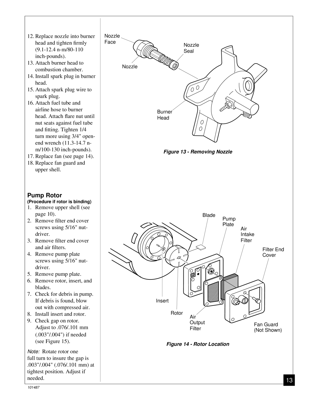
Pump Rotor
(Procedure if rotor is binding)
1.Remove upper shell (see page 10).
2.Remove filter end cover screws using 5/16" nut- driver.
3.Remove filter end cover and air filters.
4.Remove pump plate screws using 5/16" nut- driver.
5.Remove pump plate.
6.Remove rotor, insert, and blades.
7.Check for debris in pump. If debris is found, blow out with compressed air.
8.Install insert and rotor.
9.Check gap on rotor. Adjust to .076/.101 mm (.003"/.004") if needed (see Figure 15).
Note: Rotate rotor one
full turn to insure the gap is
.003"/.004" (.076/.101 mm) at tightest position. Adjust if needed.
Nozzle
Face
Nozzle
Nozzle
Seal
Burner
Head
Figure 13 - Removing Nozzle
Blade
Pump
Plate
Air
Intake
Filter
Filter End
Cover
Insert
Rotor
Air |
| |
Output | Fan Guard | |
Filter | ||
(Not Shown) | ||
| ||
Figure 14 - Rotor Location |
|
13
101487