OWNER’S OPERATION AND INSTALLATION MANUAL
MGH5000DIE, MGH6000D, MGH6000DI, MGH7000D, MGH7000DI, and MGH10000A
PORTABLE GASOLINE GENERATORS
SAFETY INFORMATION
PORTABLE GASOLINE GENERATORS
WARNINGS
PRODUCT IDENTIFICATION
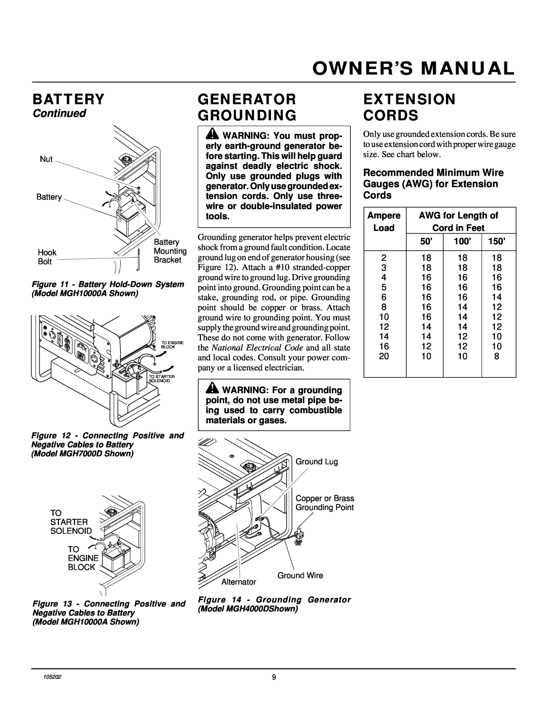
Continued
SAFETY INFORMATION
Additional Features
HIGH AND LOW TEMPERATURE OPERATION
GENERAL INFORMATION
UNPACKING
SPECIFICATIONS
FULL POWER SELECTOR SWITCH
GENERATOR FEATURES
GROUND FAULT CIRCUIT INTERRUPTER RECEPTACLE
Test Procedure
FUEL
ENGINE OIL
ENGINE CIRCUIT BREAKER
RECEPTACLE CIRCUIT BREAKER
INSTALLING BATTERY CABLES TO ENGINE
BATTERY
MOUNTING BATTERY TO GENERATOR
PORTABLE GASOLINE GENERATORS
GENERATOR GROUNDING
Recommended Minimum Wire Gauges AWG for Extension Cords
EXTENSION CORDS
BATTERY
Chart 1 - Typical Electric Appliance Wattages
STANDBY INSTALLATION TO HOME OR BUILDING
Chart
DETERMINING ELECTRICAL LOAD FOR GENERATOR
USING RECEPTACLE
POWER CORD AND PLUG REQUIREMENTS
OPERATION
GENERAL INFORMATION
STARTING
PRESTART
PORTABLE GASOLINE GENERATORS
OPERATION
HIGH ALTITUDE OPERATION
DISCONNECTING ELECTRIC LOADS
ADDING ELECTRICAL LOADS
STOPPING ENGINE
TROUBLESHOOTING
MAINTENANCE AND REPAIRS
OBSERVED PROBLEM
STORAGE
WIRING DIAGRAMS
ELECTRICAL COMPONENT SPECIFICATIONS
Resistance in Ohms
Stator
Figure 26 - Wiring Diagram, Model MGH7000D
WIRING DIAGRAMS
Figure 27 - Wiring Diagram, Model MGH10000A
PORTABLE GASOLINE GENERATORS
ACCESSORIES
TECHNICAL SERVICE
REPLACEMENT PARTS
PARTS UNDER WARRANTY
ILLUSTRATED PARTS LIST
For Models HWI3000 and MGH3000 Alternator Assembly
PORTABLE GASOLINE GENERATORS
MGH6000D, MGH6000DI MGH7000D, and MGH7000DI Alternator Assembly
For Models MGH4000D MGH4000DI, MGH5000D MGH5000DI, MGH5000DIE
ILLUSTRATED PARTS LIST
Alternator Assembly
PARTS LIST
ILLUSTRATED
For Model MGH10000A
ILLUSTRATED PARTS LIST
For Models HWI3000 and MGH3000 Roll Cage
ILLUSTRATED PARTS LIST
MGH6000D, MGH6000DI MGH7000D, and MGH7000DI Fuel Tank and Roll Cage
PORTABLE GASOLINE GENERATORS
For Models MGH4000D MGH4000DI, MGH5000D MGH5000DI, MGH5000DIE
For Models MGH4000D MGH4000DI, MGH5000D MGH5000DI, MGH5000DIE
ILLUSTRATED PARTS LIST
MGH6000D, MGH6000DI MGH7000D, and MGH7000DI Fuel Tank and Roll Cage
For models MGH4000D, MGH5000D, MGH5000DIE, and MGH6000D only
ILLUSTRATED PARTS LIST
For Model MGH10000A Fuel Tank and Roll Cage
PORTABLE GASOLINE GENERATORS
2711
ILLUSTRATED PARTS LIST
For Model MGH10000A Fuel Tank and Roll Cage
Δ Not shown Available at your local hardware store
MGH4000DI, MGH5000D
For Models MGH4000D
MGH5000DI, MGH5000DIE
MGH6000D, MGH6000DI
Panel
For Model MGH10000A Control
ILLUSTRATED PARTS LIST
† Includes reference numbers 1 through Δ Not shown
TWO-YEAR LIMITED WARRANTY GASOLINE PORTABLE GENERATORS
WARRANTY INFORMATION
INTERNATIONAL
NOT A UPC