OWNER’S MANUAL
OPERATION
GENERAL INFORMATION
This generator is not large enough to power your entire home. Do not connect generator to any existing electrical circuits. Plug items directly into generator receptacles. Do not exceed amperage rating of receptacles. Only use grounded cords.
![]() DANGER: Use only in well- vented areas. Make sure area has plenty of
DANGER: Use only in well- vented areas. Make sure area has plenty of
DANGER: Never connect gen- erator to any existing electrical circuits. The generator output will
Model MGH10000A also has a 120/240V,
Model HWI3000 has only the 120V, 20- amp duplex receptacle.
Model MGH3000 has only the 120V, 15- amp GFCI duplex receptacle.
120V,
| 120V, |
| |
| 120/240V, 20 or 30- | ||
| Amp |
| |
120 | VOLTS |
| |
|
| ||
| RESET |
| |
| TEST |
| |
| 120 |
| |
| ONLY |
| |
| 120 |
| |
| 240V |
| |
| ENM |
| |
| 00000005 |
| |
| HOURS | RESET | |
| 1/10 | ||
120V, | RESET | ||
| |||
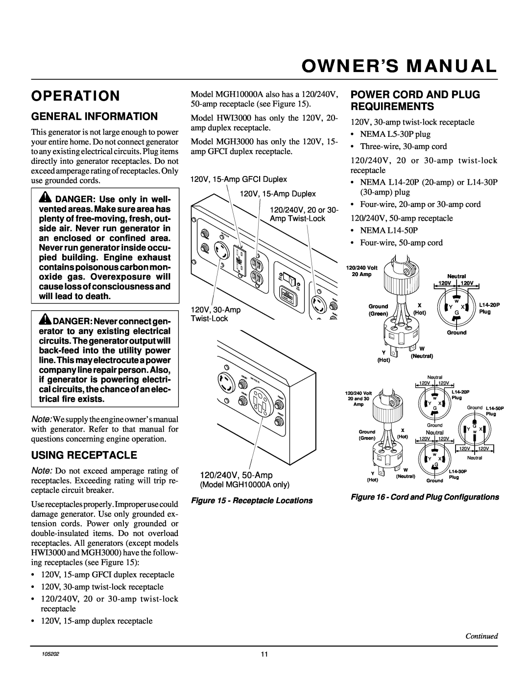
POWER CORD AND PLUG REQUIREMENTS
120V,
•NEMA
•
120/240V, 20 or
•NEMA
•
120/240V,
•NEMA
•
120/240 Volt |
|
|
|
|
20 Amp |
| Neutral |
| |
|
|
| ||
|
| 120V | 120V |
|
Ground | X |
| w | |
Y | X | |||
(Green) | (Hot) |
| G | Plug |
|
| Ground |
| |
Y | W |
|
|
|
(Neutral) |
|
|
| |
(Hot) |
|
|
| |
|
|
|
| |
if generator is powering electri- cal circuits, the chance of an elec- trical fire exists.
Note: We supply the engine owner’s manual with generator. Refer to that manual for questions concerning engine operation.
USING RECEPTACLE
Note: Do not exceed amperage rating of receptacles. Exceeding rating will trip re- ceptacle circuit breaker.
RESET | 240 | VOLTS |
|
| |
RESET |
| RESET |
|
| |
|
| RESET |
120/240V,
(Model MGH10000A only)
120/240 Volt
20 and 30
Amp
Ground (Green)
Y ![]() (Hot)
(Hot)
Neutral 120V 120V
wPlug
Y X
GGround
Plug
X | Ground | Y | G | X | |
Neutral | w | ||||
(Hot) | 120V | 120V |
|
|
|
|
|
|
| ||
|
|
| 120V |
| 120V |
|
| w | Neutral | ||
| Y | X | |||
G
W
(Neutral)Plug Ground
Use receptacles properly. Improper use could damage generator. Use only grounded ex- tension cords. Power only grounded or
•120V,
•120V,
•120/240V, 20 or
•120V,
Figure 15 - Receptacle Locations | Figure 16 - Cord and Plug Configurations |
|
Continued
105202 | 11 |