OWNER’S MANUAL
ELECTRICAL
COMPONENT
SPECIFICATIONS
|
| Resistance in Ohms |
|
|
| |
| Stator | Stator | Rotor | Rotor | Capacitor, |
|
| Main | Auxiliary | Primary | Secondary | MFD | Diodes (2) |
Model | Winding * | Winding Δ | Winding † | Winding † | 450 Volt | 800 Volt |
|
|
|
|
|
|
|
HWI3000 | 1.6 | 5.9 | 6.9 | 1.33 | 16 | 6 Amp |
MGH3000 | 1.6 | 5.9 | 6.9 | 1.33 | 16 | 6 Amp |
MGH4000D, MGH4000DI | 0.71 | 2.17 | 0.54 | 2.07 | 40 | 70 Amp |
MGH5000D, MGH5000DI | 0.54 | 1.38 | 0.61 | 2.29 | 50 | 70 Amp |
MGH5000DIE | 0.54 | 1.38 | 0.61 | 2.29 | 50 | 70 Amp |
MGH6000D, MGH6000DI | 0.37 | 1.01 | 0.68 | 2.57 | 60 | 70 Amp |
MGH7000D, MGH7000DI | 0.28 | 0.78 | 0.77 | 2.9 | 70 | 70 Amp |
MGH10000A | 0.40 | 0.90 | 0.37 | 0.50 | 80 | 70 Amp |
|
|
|
|
|
|
|
*Connect T2 (green) and T3 (black). Measure resistance between T1 (red) and T4 (yellow). Δ Resistance between brown and white leads.
† Remove diodes to check resistance.
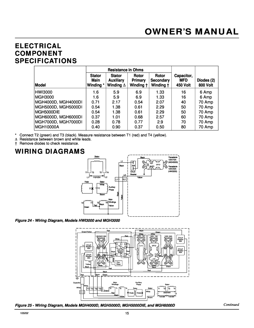
WIRING DIAGRAMS
|
| Stator |
|
|
|
| Black |
|
|
|
|
|
|
| |
|
|
|
|
|
| L1 |
|
|
|
|
|
|
| Black | 20A |
T1 | T3 |
| T2 | T4 |
|
| Circuit |
|
|
| Breaker | ||||
|
|
|
|
|
| L2 | |
| 110/120V | L2 |
|
| |||
L1 | L1 | L2 | Yellow | ||||
Rotor |
|
| Stator |
|
| ||
|
|
|
|
|
| ||
|
|
| White |
|
|
|
|
| D | C | Auxiliary |
|
|
| |
| Phase |
|
|
| |||
|
|
|
| Black | Yellow |
| |
|
|
| Brown | Main |
| ||
T2 | T1 | T3 | Black | T4 Windings |
|
| |
| Red | Yellow |
|
|
| ||
Green |
|
|
|
| |||
|
|
|
|
|
|
| |
LINE
HOT
WHITE
GFCI
Receptacle 120V/15A (MGH3000)
Receptacle 120V/20A (HWI3000)
Figure 24 - Wiring Diagram, Models HWI3000 and MGH3000
Green/Yellow |
|
| Red |
|
|
|
|
|
| Black | ||
|
|
|
|
|
|
|
|
|
| |||
|
|
|
|
|
|
|
|
|
| Red |
| White |
|
|
| 120/240V 20A |
|
|
|
|
| 120V, 15A | |||
|
|
|
| Receptacle |
| White |
|
|
| Receptacle | ||
|
|
|
|
|
|
|
|
|
|
| ||
T1 | Circuit |
|
|
|
|
| T2 |
|
| Duplex | ||
Breaker |
|
|
|
|
|
|
| |||||
| 25A |
|
|
|
|
|
| Full Pwr |
|
|
| |
|
|
|
|
|
|
|
|
|
|
| ||
|
|
|
|
| Black | Selector | Red |
| ||||
|
|
|
|
| Switch |
|
|
| ||||
|
|
|
|
|
|
|
|
|
|
| ||
| Circuit |
|
| Black |
|
|
|
|
|
| ||
| Breaker | T3 |
|
|
|
|
|
|
| |||
| 25A |
|
|
| White |
|
|
|
|
|
| |
|
|
|
|
|
|
|
|
|
|
| ||
| T4 |
|
|
|
|
| Hour |
|
|
| ||
|
|
|
|
|
|
|
|
|
| |||
| Yellow |
|
| White |
|
|
| Meter |
|
|
| |
| Black |
|
|
|
|
|
|
|
|
|
| |
|
|
|
| Red |
|
|
|
|
|
| ||
|
|
|
|
|
|
|
|
|
|
| ||
|
|
|
|
| Black |
|
|
|
|
|
|
|
Red |
|
| Black | Green |
|
|
|
|
|
|
| |
Capacitor |
|
|
|
|
| Main |
|
|
| Auxiliary | ||
White |
|
|
|
| Windings |
|
|
| Phase | |||
|
|
|
|
|
|
|
|
|
|
| ||
White | T1 | T4 | T3 | T2 | T2 |
|
| T1 | T3 | T4 | Rotor | |
|
|
| ||||||||||
|
|
|
|
| Green |
|
|
|
|
|
|
|
|
|
|
|
|
| Red |
|
|
|
| Diode | Diode |
|
|
|
|
|
| Black | Yellow |
|
|
| ||
|
|
|
|
|
|
|
|
|
|
|
| |
| Green |
|
|
| |
White |
|
|
|
| |
120V, 15A |
| 120V, 30A | Circuit | ||
Receptacle |
| Receptacle | |||
|
|
|
|
| Breaker |
|
|
|
|
| 20A |
GFCI |
|
|
|
| |
|
|
|
|
| Circuit |
|
|
|
|
| Breaker |
| WHITE |
|
|
| 20A |
HOT | White |
|
|
| |
LINE |
|
|
|
| |
Green |
|
| Green |
| |
Black |
|
|
| ||
|
|
|
| ||
Red |
|
|
|
|
|
|
|
| Stator |
| |
Stator |
| T1 | T2 | T3 | T4 |
White |
|
| 220/240V |
| |
| L1 | L2 | |||
|
|
| |||
Brown |
| 110/120V | 110/120V | ||
|
|
|
|
| |
Figure 25 - Wiring Diagram, Models MGH4000D, MGH5000D, MGH5000DIE, and MGH6000D | Continued |
|
|
105202 | 15 |