Model No. CF-30CTQAZ 1
This is the Service Manual for the following areas E …for U.K
Model No. CF-30 SERIES
Notebook Computer
How to replace the fuse
For U.K This apparatus must be earthed for your safety
Open the fuse compartment with a screw- driver and replace the fuse
LASER SAFETY INFORMATION
Page
Page
CONTENTS
Main Specifications
1 Specifications
Wireless LAN Only for model with wireless LAN
BluetoothTM Only for model with Bluetooth
23-E-1
2 Names and Functions of Part
C D E F G
Q J H K L M N O P R
Right side
Intel Core
Diagram
CF-30 Block Diagram
3 Block
4.1. Basic Procedures
4 Diagnosis Procedure
Flow Chart
4.2. Troubleshooting
5 Power-On Self Test Boot Check
Error Diagnosis by Checking Beep Signal Sound
Outline of POST
6 List of Error Codes Only when the port replicator is connected
02F0 CPU ID
1-3. When you execute the enhancing test
7 Self Diagnosis Test
1. Beginning of self-diagnosis test 1-1. Setting of content of setup
1-2. When you execute an automatic test
2. Operation of PC-Diagnostic Utility
2-2. PC-Diagnostic utility End method
2-3. The content of the setup is returned to the setting of the user
2-1. Selection of tested device
7.1. Test Item and Division of trouble
Enhancing
Place with possibili
Test Item
8 Wiring Connection Diagram
9.1.1
9 Disassembly/Reassembly
Disassembly Instructions
9.1.2. Removing the Battery Pack and HDD
9.1.3. Removing the HDD
9.1.4. Removing the KB Cover, Hinge Cover L, Hinge Cover R and Key
board
9.1.6. Removing the GPS PCB and Blue- tooth PCB
9.1.5. Removing the KB Cable Cover and LCD Cable Cover
9.1.8. Removing the USB PCB and Antenna PCB
9.1.7. Removing the DIMM Cover and Bot- tom Cover
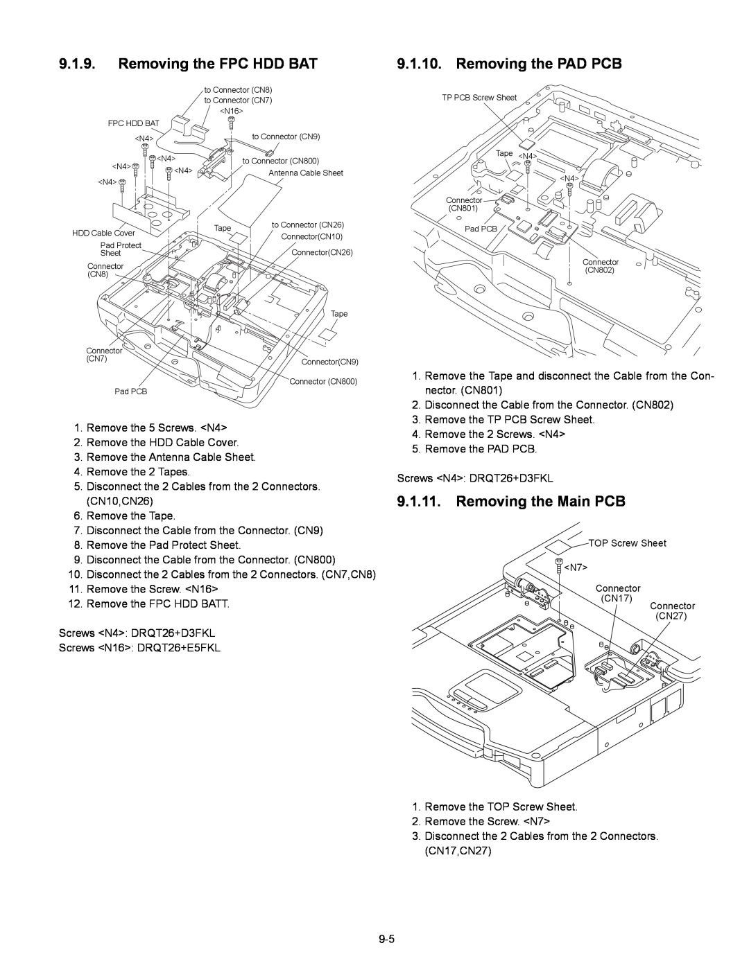
9.1.9. Removing the FPC HDD BAT
9.1.10. Removing the PAD PCB
9.1.11. Removing the Main PCB
CN400,CN401 11. Remove the 2 Screws. N5 12. Remove the 2 Screws. N21
1. Open the Connector Cover and Lid Cover
9.1.12. Removing the SD PCB, Express Card
9.1.13. Removing the I/O PCB
and PCMCIA Card
9.1.15. Removing the Handle and Power SW
9.1.16. Removing the Display Unit
9.1.17. Removing the LCD Rear Cabinet
Hinge L and R
9.1.19. Removing the Antenna PCB L and R
9.1.18. Removing the Inverter PCB, TS PCB and LCD Unit
Safety Working
9.2. Reassembly Instructions
9.2.1. Attention when CF-30 series is repaired
9.2.2. Setting the Antenna PCB L and R
Inverter-PCB
9.2.3. Setting the Inverter PCB, TS PCB and LCD Unit
9.2.4. Setting the LCD Rear Cabinet, Hinge L and R
9.2.6. Setting the Handle and Power SW
9.2.5. Setting the Display Unit
Attach it not to overlap the SW leg
Attach the Tape
Attach the Sheet
SW-LED FPC Ass’y
Cover
Q Assembly of Power SW
Q Assembly of Palm Top Cover
9-16
9.2.9
Setting the I/O PCB
Setting the SD PCB, Express Card
9.2.8
9.2.10. Setting the Main PCB
9-19
N7 Connector CN17
Connector CN27
24. Fix the Screw. N7 25. Attach the TOP Screws
9-20
Q Assembly of LAN, Modem and MDC
Q Assembly of Main PCB
12 Safety Working
9.2.11. Setting the PAD PCB
9.2.12. Setting the FPC HDD BAT
Page
9.2.13. Setting the USB PCB and Antenna PCB
9-25
Q Assembly of USB PCB and Antenna PCB
9.2.14. Setting the DIMM Cover and Bottom Cover
Q Preparation of DIMM Cover
9-27
Attach the Keyboard Cable Cover Cushion
3. Fix the GPS Ass’y using the 4 Screws. N12
9.2.15. Setting the GPS PCB and Bluetooth PCB
1. Fix the GPS BT Angle and GPS PCB using the 2 Screws. N11
2. Connect the Cable to the Connector on GPS PCB
to Connector
9.2.16. Setting the KB Cable Cover, Keyboard and LCD Cable Cover
7.2.18. Setting the HDD
9-31
Lead Wire
Important Parts Heater for Safety
Q Preparation oh HDD ASSY
HDD Ass’y
1. Apply the load when attaching the parts. 20N to 30N 2 to 3Kgf/cm2
HDD Damper Ass’y
Push and bend
HDD Thermal Plate
Do not bend it at a sharp angle to put natural R
Keep the space to secure the air vent
Lower Case
HDD Side Damper
B-B SEC
A-A SEC
Avoid getting HDD under the side damper when inserting HDD
9.2.19. Setting the Battery Pack and HDD Pack
1. Set the HDD Pack 2. Set the Battery Pack
9-36
Screw tightening torque
10 E xploded View
T 0.90 ± 0.05 N.m 9.0 ± 0.5 kgf.cm
A 0.19 ± 0.02 N.m 2.0 ± 0.2 kgf.cm B 0.45 ± 0.05 N.m 4.5 ± 0.5 kgf.cm
G 1.47 ± 0.20 N.m 15.0 ± 2.0 kgf.cm L 0.2 ± 0.02 N.m 2.0 ± 0.2kgf.cm
Q 0.22 ± 0.02 N.m 2.2 ± 0.2 kgf.cm R 0.30 ± 0.05 N.m 3.0 ± 0.5 kgf.cm
Screw tightening torque
K2-32
B 0.45 + 0.05 N.m 4.5 + 0.5 kgf.cm P 0.8 + 0.1N.m 8.0 + 1.0 kgf.cm
R 0.3 + 0.05 N.m 3.0 + 0.5 kgf.cm S 0.19 + 0.05 N.m 2.0 + 0.5 kgf.cm
10-4
K9-1-4
K10-2
K56 E35-3E35-1 E35-8 E35-4 E35-6 E35-3 E35-7 E35-4 A E35-10 E35-9
E35-5
E35 K54 E35-2 E15
A E35-10
Screw tightening torque
Replacement Parts List
CF-30CTQAZxx
REF. NO and AREA
FAX +44-029-20736250
Accessories
Packing Material
Mechanical Parts
DFHR6257ZA
WIRELESS SW CASE
WIRELESS SW KNOB
K2-2-4
DFHR3E58ZA
POWER SW CUSHION
WIRELESS SW FPC
K2-10-4
K9-2-1
K9-2
DFWV84A0277
TOUCH SCREEN PANEL KIT
DFMC0873ZA
POWER SW LED PANEL
DFMC0863ZA
INV SHIELD CASE
K123
K122
DFMD4067ZA-0
SERIAL COVER PLATE
Replacement Parts List
Note Important Safety Notice
11-8
F1G1A104A014
11-9
11-10
D 8, 9, 10, 11, 12, 13, 14
IC 32, 58, 59, 61, 62, 68
Q 3, 4, 16, 30, 31, 32, 33
11-11
IC 65, 72, 96, 101, 102
Q 1, 2, 36, 52, 53, 59, 66
R 49, 117, 151, 152, 209
11-12
R 21, 47, 99, 100, 101
R 40, 104, 109, 136, 150
R 170
11-13
IO PCB
MP PCB
11-14
HDD PACK PCB
SD PCB
P-SW PCB
BAT FPC
11-16
BLUETOOTH PCB