Model No. CF-30 SERIES
This is the Service Manual for the following areas E …for U.K
Notebook Computer
Model No. CF-30CTQAZ 1
How to replace the fuse
For U.K This apparatus must be earthed for your safety
Open the fuse compartment with a screw- driver and replace the fuse
LASER SAFETY INFORMATION
Page
Page
CONTENTS
Main Specifications
1 Specifications
Wireless LAN Only for model with wireless LAN
BluetoothTM Only for model with Bluetooth
23-E-1
2 Names and Functions of Part
C D E F G
Q J H K L M N O P R
Right side
CF-30 Block Diagram
Diagram
3 Block
Intel Core
4.1. Basic Procedures
4 Diagnosis Procedure
Flow Chart
4.2. Troubleshooting
5 Power-On Self Test Boot Check
Error Diagnosis by Checking Beep Signal Sound
Outline of POST
6 List of Error Codes Only when the port replicator is connected
02F0 CPU ID
1. Beginning of self-diagnosis test 1-1. Setting of content of setup
7 Self Diagnosis Test
1-2. When you execute an automatic test
1-3. When you execute the enhancing test
2. Operation of PC-Diagnostic Utility
2-2. PC-Diagnostic utility End method
2-3. The content of the setup is returned to the setting of the user
2-1. Selection of tested device
7.1. Test Item and Division of trouble
Enhancing
Place with possibili
Test Item
8 Wiring Connection Diagram
Disassembly Instructions
9 Disassembly/Reassembly
9.1.2. Removing the Battery Pack and HDD
9.1.1
9.1.3. Removing the HDD
9.1.4. Removing the KB Cover, Hinge Cover L, Hinge Cover R and Key
board
9.1.6. Removing the GPS PCB and Blue- tooth PCB
9.1.5. Removing the KB Cable Cover and LCD Cable Cover
9.1.8. Removing the USB PCB and Antenna PCB
9.1.7. Removing the DIMM Cover and Bot- tom Cover
9.1.9. Removing the FPC HDD BAT
9.1.10. Removing the PAD PCB
9.1.11. Removing the Main PCB
CN400,CN401 11. Remove the 2 Screws. N5 12. Remove the 2 Screws. N21
9.1.13. Removing the I/O PCB
9.1.12. Removing the SD PCB, Express Card
and PCMCIA Card
1. Open the Connector Cover and Lid Cover
9.1.15. Removing the Handle and Power SW
9.1.16. Removing the Display Unit
9.1.17. Removing the LCD Rear Cabinet
Hinge L and R
9.1.19. Removing the Antenna PCB L and R
9.1.18. Removing the Inverter PCB, TS PCB and LCD Unit
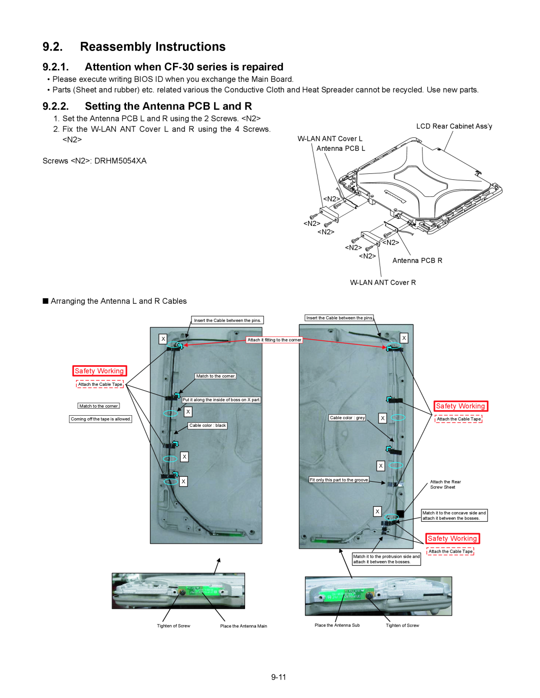
9.2.1. Attention when CF-30 series is repaired
9.2. Reassembly Instructions
9.2.2. Setting the Antenna PCB L and R
Safety Working
Inverter-PCB
9.2.3. Setting the Inverter PCB, TS PCB and LCD Unit
9.2.4. Setting the LCD Rear Cabinet, Hinge L and R
9.2.6. Setting the Handle and Power SW
9.2.5. Setting the Display Unit
Attach the Sheet
Attach the Tape
SW-LED FPC Ass’y
Attach it not to overlap the SW leg
Q Assembly of Palm Top Cover
Q Assembly of Power SW
9-16
Cover
Setting the SD PCB, Express Card
Setting the I/O PCB
9.2.8
9.2.9
9.2.10. Setting the Main PCB
Connector CN27
N7 Connector CN17
24. Fix the Screw. N7 25. Attach the TOP Screws
9-19
Q Assembly of Main PCB
Q Assembly of LAN, Modem and MDC
12 Safety Working
9-20
9.2.11. Setting the PAD PCB
9.2.12. Setting the FPC HDD BAT
Page
9.2.13. Setting the USB PCB and Antenna PCB
9-25
Q Assembly of USB PCB and Antenna PCB
9.2.14. Setting the DIMM Cover and Bottom Cover
Q Preparation of DIMM Cover
9-27
Attach the Keyboard Cable Cover Cushion
1. Fix the GPS BT Angle and GPS PCB using the 2 Screws. N11
9.2.15. Setting the GPS PCB and Bluetooth PCB
2. Connect the Cable to the Connector on GPS PCB
3. Fix the GPS Ass’y using the 4 Screws. N12
to Connector
9.2.16. Setting the KB Cable Cover, Keyboard and LCD Cable Cover
7.2.18. Setting the HDD
Important Parts Heater for Safety
Lead Wire
Q Preparation oh HDD ASSY
9-31
HDD Damper Ass’y
1. Apply the load when attaching the parts. 20N to 30N 2 to 3Kgf/cm2
Push and bend
HDD Ass’y
HDD Thermal Plate
Do not bend it at a sharp angle to put natural R
Keep the space to secure the air vent
B-B SEC
HDD Side Damper
A-A SEC
Lower Case
Avoid getting HDD under the side damper when inserting HDD
9.2.19. Setting the Battery Pack and HDD Pack
1. Set the HDD Pack 2. Set the Battery Pack
9-36
Screw tightening torque
10 E xploded View
G 1.47 ± 0.20 N.m 15.0 ± 2.0 kgf.cm L 0.2 ± 0.02 N.m 2.0 ± 0.2kgf.cm
A 0.19 ± 0.02 N.m 2.0 ± 0.2 kgf.cm B 0.45 ± 0.05 N.m 4.5 ± 0.5 kgf.cm
Q 0.22 ± 0.02 N.m 2.2 ± 0.2 kgf.cm R 0.30 ± 0.05 N.m 3.0 ± 0.5 kgf.cm
T 0.90 ± 0.05 N.m 9.0 ± 0.5 kgf.cm
Screw tightening torque
R 0.3 + 0.05 N.m 3.0 + 0.5 kgf.cm S 0.19 + 0.05 N.m 2.0 + 0.5 kgf.cm
B 0.45 + 0.05 N.m 4.5 + 0.5 kgf.cm P 0.8 + 0.1N.m 8.0 + 1.0 kgf.cm
10-4
K2-32
K9-1-4
K10-2
E35 K54 E35-2 E15
E35-5
A E35-10
K56 E35-3E35-1 E35-8 E35-4 E35-6 E35-3 E35-7 E35-4 A E35-10 E35-9
Screw tightening torque
Replacement Parts List
CF-30CTQAZxx
REF. NO and AREA
Packing Material
Accessories
Mechanical Parts
FAX +44-029-20736250
WIRELESS SW KNOB
WIRELESS SW CASE
K2-2-4
DFHR6257ZA
WIRELESS SW FPC
POWER SW CUSHION
K2-10-4
DFHR3E58ZA
DFWV84A0277
K9-2
TOUCH SCREEN PANEL KIT
K9-2-1
DFMC0863ZA
POWER SW LED PANEL
INV SHIELD CASE
DFMC0873ZA
DFMD4067ZA-0
K122
SERIAL COVER PLATE
K123
Replacement Parts List
Note Important Safety Notice
11-8
F1G1A104A014
11-9
11-10
D 8, 9, 10, 11, 12, 13, 14
IC 32, 58, 59, 61, 62, 68
IC 65, 72, 96, 101, 102
11-11
Q 1, 2, 36, 52, 53, 59, 66
Q 3, 4, 16, 30, 31, 32, 33
R 21, 47, 99, 100, 101
11-12
R 40, 104, 109, 136, 150
R 49, 117, 151, 152, 209
R 170
11-13
IO PCB
MP PCB
11-14
P-SW PCB
SD PCB
BAT FPC
HDD PACK PCB
11-16
BLUETOOTH PCB