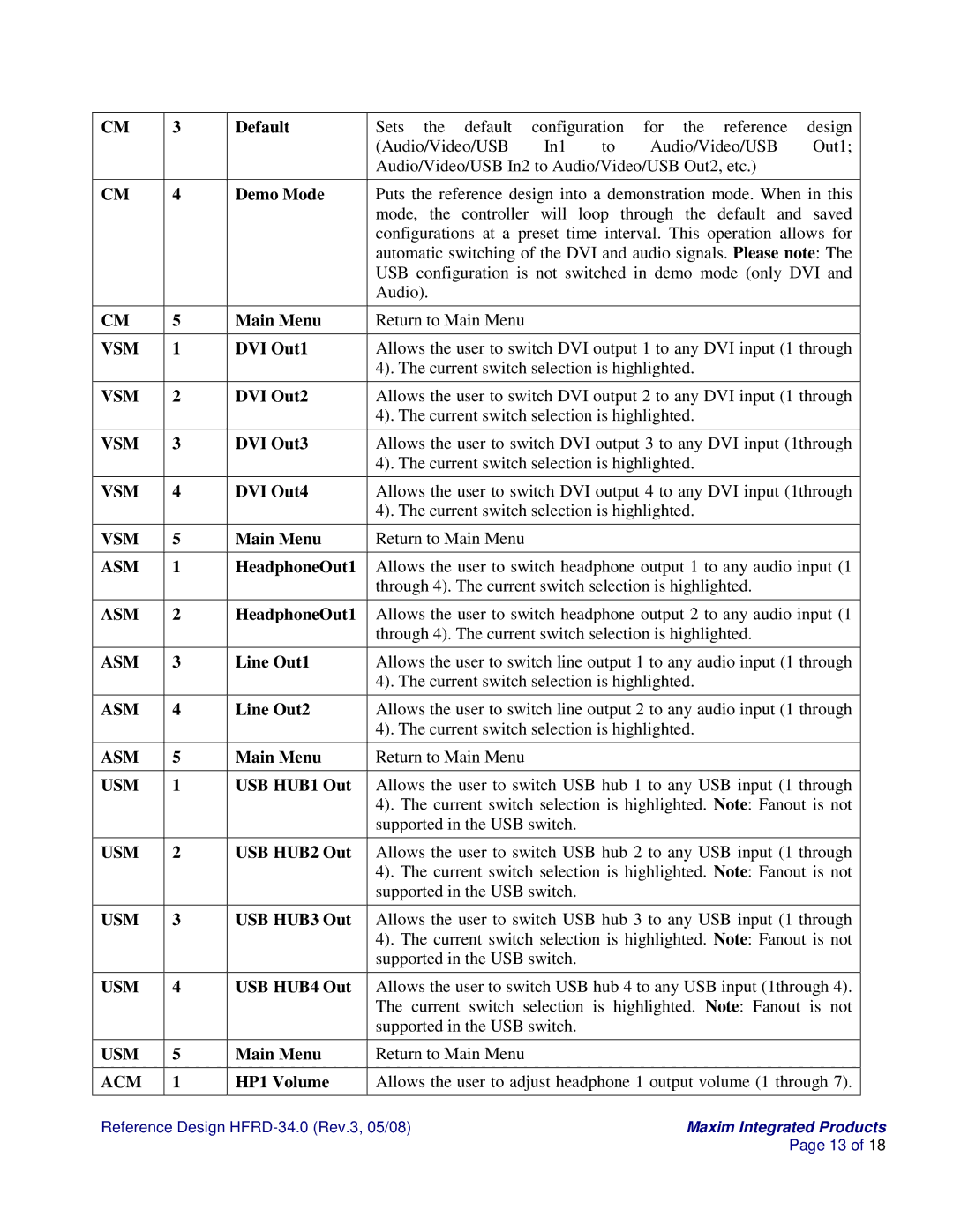
CM

3

Default

Sets the default configuration for the reference design


(Audio/Video/USB

In1

to

Audio/Video/USB

Out1;


Audio/Video/USB In2 to Audio/Video/USB Out2, etc.)


CM

4

Demo Mode

Puts the reference design into a demonstration mode. When in this


mode, the controller will loop through the default and saved


configurations at a preset time interval. This operation allows for


automatic switching of the DVI and audio signals. Please note: The


USB configuration is not switched in demo mode (only DVI and


Audio).


CM

5

Main Menu

Return to Main Menu


VSM

1

DVI Out1

Allows the user to switch DVI output 1 to any DVI input (1 through


4). The current switch selection is highlighted.


VSM

2

DVI Out2

Allows the user to switch DVI output 2 to any DVI input (1 through


4). The current switch selection is highlighted.


VSM

3

DVI Out3

Allows the user to switch DVI output 3 to any DVI input (1through


4). The current switch selection is highlighted.


VSM

4

DVI Out4

Allows the user to switch DVI output 4 to any DVI input (1through


4). The current switch selection is highlighted.


VSM

5

Main Menu

Return to Main Menu


ASM

1

HeadphoneOut1

Allows the user to switch headphone output 1 to any audio input (1


through 4). The current switch selection is highlighted.


ASM

2

HeadphoneOut1

Allows the user to switch headphone output 2 to any audio input (1


through 4). The current switch selection is highlighted.


ASM

3

Line Out1

Allows the user to switch line output 1 to any audio input (1 through


4). The current switch selection is highlighted.


ASM

4

Line Out2

Allows the user to switch line output 2 to any audio input (1 through


4). The current switch selection is highlighted.


ASM

5

Main Menu

Return to Main Menu


USM

1

USB HUB1 Out

Allows the user to switch USB hub 1 to any USB input (1 through


4). The current switch selection is highlighted. Note: Fanout is not


supported in the USB switch.


USM

2

USB HUB2 Out

Allows the user to switch USB hub 2 to any USB input (1 through


4). The current switch selection is highlighted. Note: Fanout is not


supported in the USB switch.


USM

3

USB HUB3 Out

Allows the user to switch USB hub 3 to any USB input (1 through


4). The current switch selection is highlighted. Note: Fanout is not


supported in the USB switch.


USM

4

USB HUB4 Out

Allows the user to switch USB hub 4 to any USB input (1through 4).


The current switch selection is highlighted. Note: Fanout is not


supported in the USB switch.


USM

5

Main Menu

Return to Main Menu


ACM

1

HP1 Volume

Allows the user to adjust headphone 1 output volume (1 through 7).


Reference Design HFRD-34.0 (Rev.3, 05/08)


Maxim Integrated Products


Page 13 of 18

Page 13
Image 13
Maxim HFRD-34.0 manual Vsm

HFRD-34.0 specifications

Maxim HFRD-34.0 is a cutting-edge device designed to meet the growing demands for high-performance performance in various industrial and commercial applications. With its state-of-the-art features and technology, the HFRD-34.0 aims to deliver enhanced efficiency, reliability, and versatility for users.

One of the standout features of the HFRD-34.0 is its advanced data processing capabilities. Equipped with a powerful microcontroller, it offers rapid data acquisition and analysis, ensuring real-time monitoring of critical parameters. This capability is essential for industries that require immediate responses to dynamic conditions, such as manufacturing, energy management, and environmental monitoring.

The device also benefits from its robust communication options. The HFRD-34.0 supports various protocols, including Modbus, CAN, and Ethernet, facilitating seamless integration with existing systems and enabling remote access and control. This connectivity is crucial for industries that rely on IoT (Internet of Things) technologies, as it enables users to gather insights from multiple devices and optimize operations.

In terms of durability, the HFRD-34.0 is built to withstand harsh environmental conditions. With a rugged housing and an IP65 rating for dust and water resistance, it can operate effectively in extreme temperatures and challenging environments. This resilience makes it an ideal choice for applications in oil and gas, mining, and other heavy industries.

Another key characteristic of the HFRD-34.0 is its energy efficiency. The device is designed to consume minimal power while delivering maximum output, making it environmentally friendly and cost-effective for users. Coupled with its intelligent power management features, the HFRD-34.0 ensures sustained performance without compromising energy consumption.

Additionally, the HFRD-34.0 features a user-friendly interface, making it accessible to operators with varying levels of technical expertise. The intuitive design allows for easy setup and configuration, minimizing downtime and enhancing operational efficiency.

In conclusion, the Maxim HFRD-34.0 is a versatile and resilient device that stands out for its advanced data processing, robust communication options, durability, energy efficiency, and user-friendly design. Its range of features positions it as a valuable asset for industries seeking to enhance their operational capabilities while embracing modern technological advancements.