INTERFACE COMMANDS
InitializationCommands
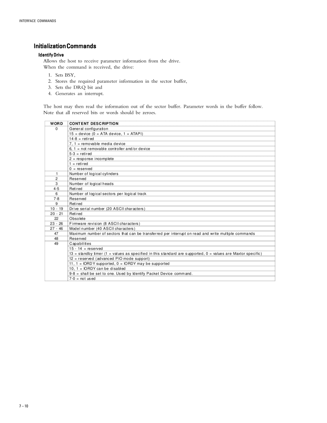
Identify Drive
Allows the host to receive parameter information from the drive.
When the command is received, the drive:
1.Sets BSY,
2.Stores the required parameter information in the sector buffer,
3.Sets the DRQ bit and
4.Generates an interrupt.
The host may then read the information out of the sector buffer. Parameter words in the buffer follow. Note that all reserved bits or words should be zeroes.
W OR D | CONT ENT DESC RIPTION |
0 | General configuration |
| 15 = device (0 = ATA device, 1 = ATAPI) |
| 14 |
| 7, 1 = removable media device |
| 6, 1 = not removable controller and/or device |
| |
| 2 = response incomplete |
| 1 = retired |
| 0 = reserved |
1 | Number of logical cylinders |
2 | Reserved |
3 | Number of logical heads |
Retired | |
6 | Number of logical sectors per logic al track |
Reserved | |
9 | Retired |
10 - 19 | Drive serial number (20 ASCII characters ) |
20 - 21 | Retired |
22 | Obsolete |
23 - 26 | F irmware revision (8 ASCII characters ) |
27 - 46 | Model number (40 ASCII characters ) |
47 | Maximum number of sectors that c an be transferred per interrupt on read and write multiple commands |
48 | Reserved |
49 | C apabilities |
| 15 - 14 = reserved |
| 13 = s tandby timer (1 = values as specified in this s tandard are s upported, 0 = values are Maxtor specific ) |
| 12 = reserved (advanc ed PIO mode support) |
| 11, 1 = IORD Y supported, 0 = IORDY may be supported |
| 10, 1 = IORDY can be disabled |
| |
|
7 – 10