SECTION VII
PROCEDURE FOR FUNCTIONAL CHECK
OF REPLACEMENT COMPONENTS
1.Microprocessor Controller (Computer) Board
a.Upon completing installation of the replacement microprocessor controller (computer) board, reestablish power to the dryer.
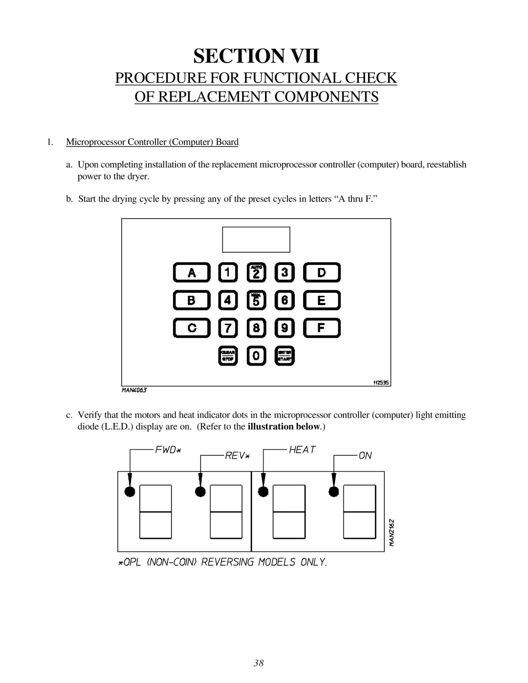
b.Start the drying cycle by pressing any of the preset cycles in letters “A thru F.”
c.Verify that the motors and heat indicator dots in the microprocessor controller (computer) light emitting diode (L.E.D.) display are on. (Refer to the illustration below.)
38