Component Testing Procedures
!WARNING
To avoid electrical shock, personal injury, or death: disconnect power supply before servicing, unless testing requires it.
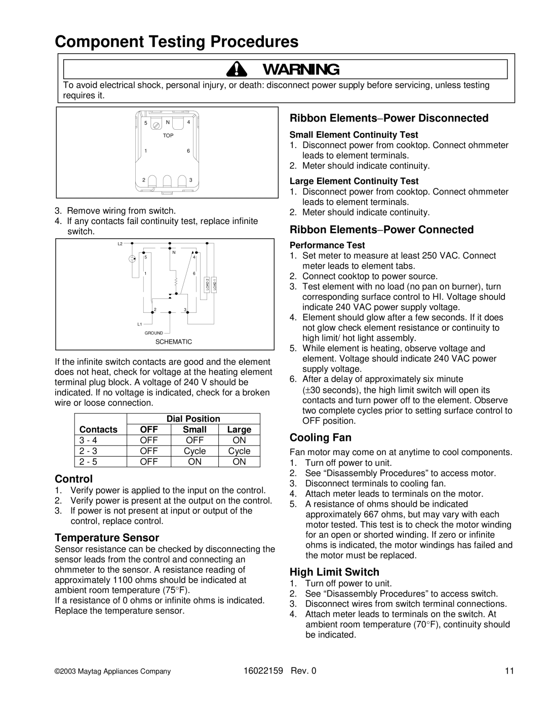
5 N 4
TOP
16
23
3.Remove wiring from switch.
4.If any contacts fail continuity test, replace infinite switch.
Ribbon Elements−Power Disconnected
Small Element Continuity Test
1.Disconnect power from cooktop. Connect ohmmeter leads to element terminals.
2.Meter should indicate continuity.
Large Element Continuity Test
1.Disconnect power from cooktop. Connect ohmmeter leads to element terminals.
2.Meter should indicate continuity.
Ribbon Elements−Power Connected
L2 |
|
|
| N |
|
5 | 4 |
|
1 | 6 |
|
| LOAD 2 | LOAD 1 |
23
L1
GROUND
SCHEMATIC
If the infinite switch contacts are good and the element does not heat, check for voltage at the heating element terminal plug block. A voltage of 240 V should be indicated. If no voltage is indicated, check for a broken wire or loose connection.
|
| Dial Position |
| ||
Contacts | OFF |
| Small |
| Large |
3 - 4 | OFF |
| OFF |
| ON |
2 - 3 | OFF |
| Cycle |
| Cycle |
2 - 5 | OFF |
| ON |
| ON |
Control
1.Verify power is applied to the input on the control.
2.Verify power is present at the output on the control.
3.If power is not present at input or output of the control, replace control.
Temperature Sensor
Sensor resistance can be checked by disconnecting the sensor leads from the control and connecting an ohmmeter to the sensor. A resistance reading of approximately 1100 ohms should be indicated at ambient room temperature (75 F).
If a resistance of 0 ohms or infinite°ohms is indicated. Replace the temperature sensor.
16022159
Performance Test
1.Set meter to measure at least 250 VAC. Connect meter leads to element tabs.
2.Connect cooktop to power source.
3.Test element with no load (no pan on burner), turn corresponding surface control to HI. Voltage should indicate 240 VAC power supply voltage.
4.Element should glow after a few seconds. If it does not glow check element resistance or continuity to high limit/ hot light assembly.
5.While element is heating, observe voltage and element. Voltage should indicate 240 VAC power supply voltage.
6.After a delay of approximately six minute
(±30 seconds), the high limit switch will open its contacts and turn power off to the element. Observe two complete cycles prior to setting surface control to OFF position.
Cooling Fan
Fan motor may come on at anytime to cool components.
1.Turn off power to unit.
2.See “Disassembly Procedures” to access motor.
3.Disconnect terminals to cooling fan.
4.Attach meter leads to terminals on the motor.
5.A resistance of ohms should be indicated approximately 667 ohms, but may vary with each motor tested. This test is to check the motor winding for an open or shorted winding. If zero or infinite ohms is indicated, the motor windings has failed and the motor must be replaced.
High Limit Switch
1.Turn off power to unit.
2.See “Disassembly Procedures” to access switch.
3.Disconnect wires from switch terminal connections.
4.Attach meter leads to terminals on the switch. At
ambient room temperature (70 F), continuity should be indicated.
Rev. 0 | ° | 11 |