Setup, con’t
Trigger B Voltage (Power Control)
The Rear Panel Trigger B Jack can provide either a 5 or 12 Volt Output when activated, with 5 Volts as the default. McIntosh Components with Power Control utilize 5 Volts;
1.Press the SETUP
2.Rotate the MENU Control until the words “TRIGB LVL 5V” appears. Refer to figure 16.
Figure 16
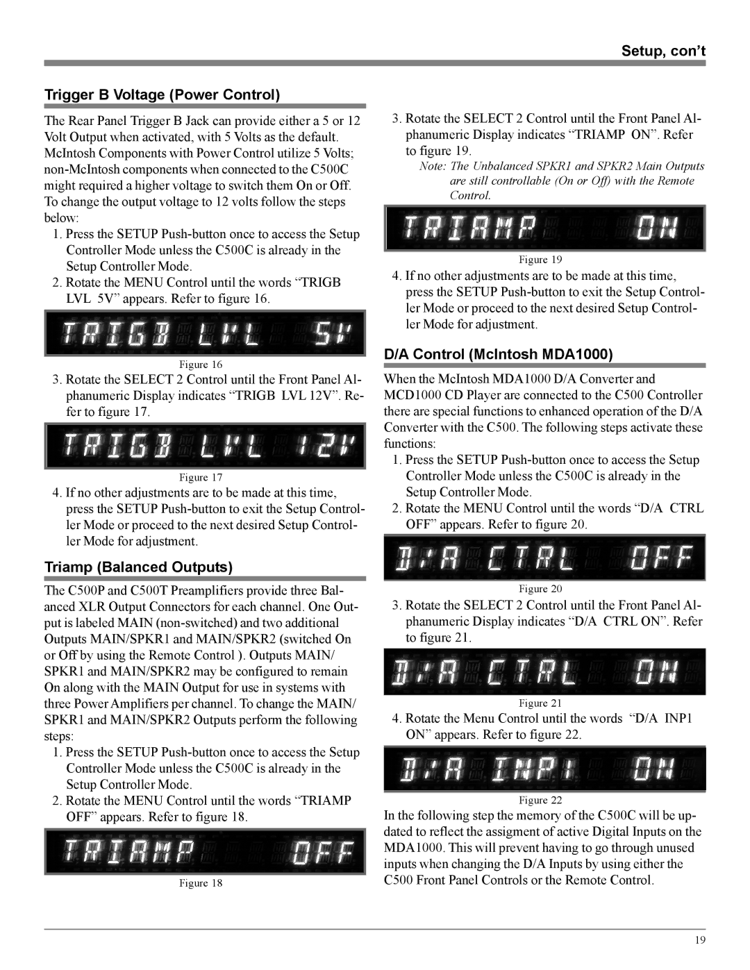
3.Rotate the SELECT 2 Control until the Front Panel Al- phanumeric Display indicates “TRIGB LVL 12V”. Re- fer to figure 17.
Figure 17
4.If no other adjustments are to be made at this time, press the SETUP
Triamp (Balanced Outputs)
The C500P and C500T Preamplifiers provide three Bal- anced XLR Output Connectors for each channel. One Out- put is labeled MAIN
1.Press the SETUP
2.Rotate the MENU Control until the words “TRIAMP OFF” appears. Refer to figure 18.
Figure 18
3.Rotate the SELECT 2 Control until the Front Panel Al- phanumeric Display indicates “TRIAMP ON”. Refer to figure 19.
Note: The Unbalanced SPKR1 and SPKR2 Main Outputs are still controllable (On or Off) with the Remote Control.
Figure 19
4.If no other adjustments are to be made at this time, press the SETUP
D/A Control (McIntosh MDA1000)
When the McIntosh MDA1000 D/A Converter and MCD1000 CD Player are connected to the C500 Controller there are special functions to enhanced operation of the D/A Converter with the C500. The following steps activate these functions:
1.Press the SETUP
2.Rotate the MENU Control until the words “D/A CTRL OFF” appears. Refer to figure 20.
Figure 20
3.Rotate the SELECT 2 Control until the Front Panel Al- phanumeric Display indicates “D/A CTRL ON”. Refer to figure 21.
Figure 21
4.Rotate the Menu Control until the words “D/A INP1 ON” appears. Refer to figure 22.
Figure 22
In the following step the memory of the C500C will be up- dated to reflect the assigment of active Digital Inputs on the MDA1000. This will prevent having to go through unused inputs when changing the D/A Inputs by using either the C500 Front Panel Controls or the Remote Control.
19