|
|
|
|
| Installation | |
Installation |
|
|
|
|
|
|
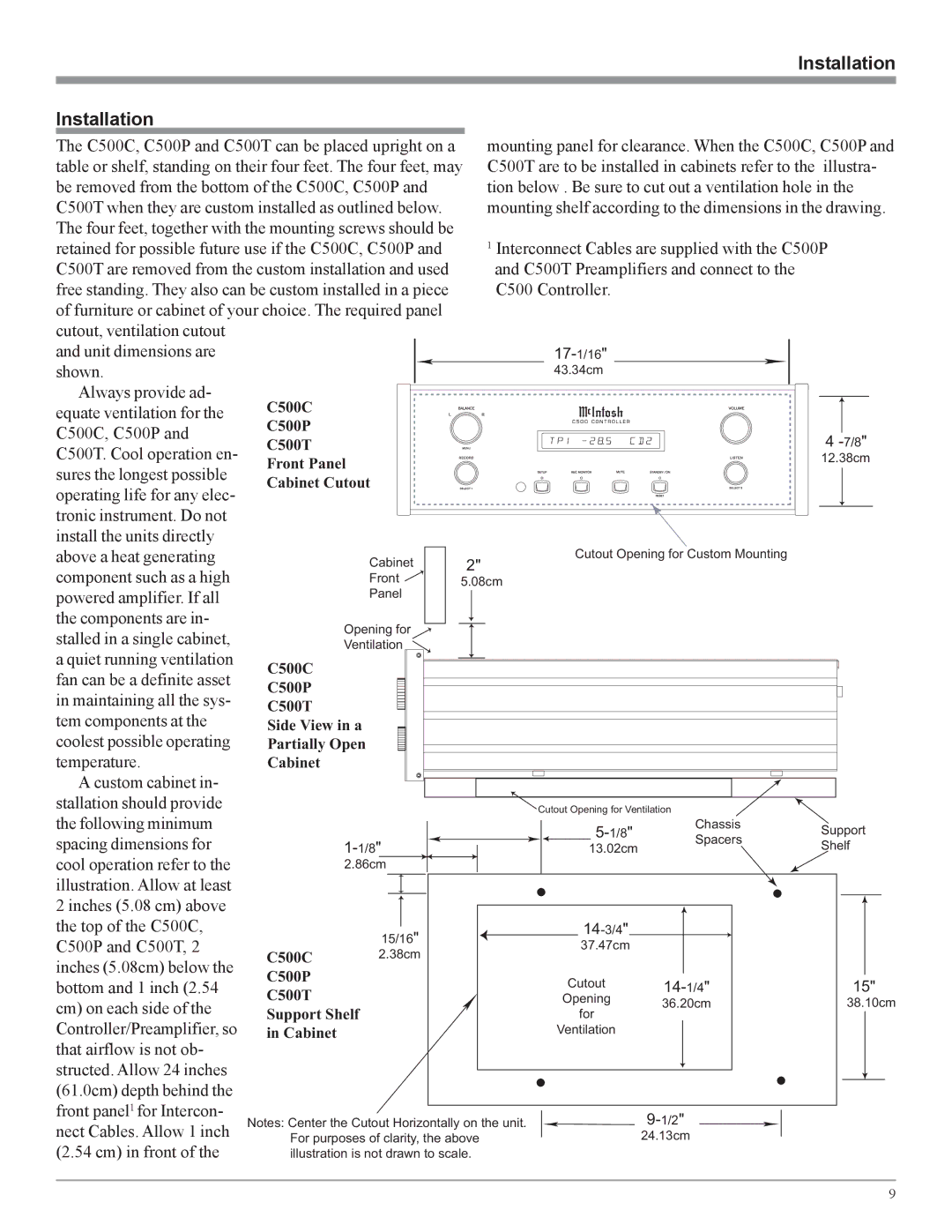
The C500C, C500P and C500T can be placed upright on a |
| mounting panel for clearance. When the C500C, C500P and | ||||
table or shelf, standing on their four feet. The four feet, may | C500T are to be installed in cabinets refer to the | illustra- | ||||
be removed from the bottom of the C500C, C500P and |
| tion below . Be sure to cut out a ventilation hole in the | ||||
C500T when they are custom installed as outlined below. |
| mounting shelf according to the dimensions in the drawing. | ||||
The four feet, together with the mounting screws should be |
|
|
|
| ||
retained for possible future use if the C500C, C500P and |
| 1 Interconnect Cables are supplied with the C500P | ||||
C500T are removed from the custom installation and used |
| and C500T Preamplifiers and connect to the |
| |||
free standing. They also can be custom installed in a piece |
| C500 Controller. |
|
| ||
of furniture or cabinet of your choice. The required panel |
|
|
|
| ||
cutout, ventilation cutout |
|
|
|
|
|
|
and unit dimensions are |
|
|
|
|
| |
shown. |
|
|
| 43.34cm |
|
|
Always provide ad- | C500C |
|
|
|
|
|
equate ventilation for the |
|
|
|
|
| |
C500C, C500P and | C500P |
|
|
|
| 4 |
C500T |
|
|
|
| ||
C500T. Cool operation en- |
|
|
|
| ||
Front Panel |
|
|
| 12.38cm | ||
sures the longest possible |
|
|
| |||
Cabinet Cutout |
|
|
|
| ||
operating life for any elec- |
|
|
|
| ||
|
|
|
|
|
| |
tronic instrument. Do not |
|
|
|
|
|
|
install the units directly |
|
|
|
|
|
|
above a heat generating |
| Cabinet | 2" | Cutout Opening for Custom Mounting |
| |
component such as a high |
|
|
|
| ||
| Front | 5.08cm |
|
| ||
powered amplifier. If all |
| Panel |
|
|
|
|
the components are in- |
| Opening for |
|
|
|
|
stalled in a single cabinet, |
|
|
|
|
| |
| Ventilation |
|
|
|
| |
a quiet running ventilation | C500C |
|
|
|
|
|
fan can be a definite asset |
|
|
|
|
| |
C500P |
|
|
|
|
| |
in maintaining all the sys- |
|
|
|
|
| |
C500T |
|
|
|
|
| |
tem components at the |
|
|
|
|
| |
Side View in a |
|
|
|
| ||
coolest possible operating | Partially Open |
|
|
|
| |
temperature. | Cabinet |
|
|
|
|
|
A custom cabinet in- |
|
|
|
|
|
|
stallation should provide |
|
|
| Cutout Opening for Ventilation |
| |
the following minimum |
|
|
| Chassis | Support | |
spacing dimensions for |
|
|
| Spacers | ||
|
| 13.02cm | Shelf | |||
|
|
| ||||
cool operation refer to the |
| 2.86cm |
|
|
|
|
illustration. Allow at least |
|
|
|
|
|
|
2 inches (5.08 cm) above |
|
|
|
|
|
|
the top of the C500C, |
| 15/16" |
|
|
| |
C500P and C500T, 2 |
|
| 37.47cm |
|
| |
C500C | 2.38cm |
|
|
| ||
inches (5.08cm) below the |
|
|
|
| ||
C500P |
|
| Cutout |
| 15" | |
bottom and 1 inch (2.54 |
|
| ||||
C500T |
|
| ||||
cm) on each side of the |
|
| Opening | 36.20cm | 38.10cm | |
Support Shelf |
| |||||
| for |
|
| |||
Controller/Preamplifier, so | in Cabinet |
|
| Ventilation |
|
|
that airflow is not ob- |
|
|
|
|
|
|
structed. Allow 24 inches |
|
|
|
|
|
|
(61.0cm) depth behind the |
|
|
|
|
|
|
front panel1 for Intercon- | Notes: Center the Cutout Horizontally on the unit. |
| ||||
nect Cables. Allow 1 inch |
| |||||
For purposes of clarity, the above |
| 24.13cm |
| |||
(2.54 cm) in front of the | illustration is not drawn to scale. |
|
|
| ||
9