- 6 -
12vDC Outlet
The 12vDC Outlet accepts a #607 Power Cord (See OPTIONAL ACCESSORIES, page 12) for powering the 16" Starfinder Equatorial Telescope from a 12vDC automobile cigarette lighter plug. While the recommended supply voltage is 12vDC, the telescope will operate in a range of
COLLIMATION OF THE OPTICAL SYSTEM
After the secondary mirror assembly has been installed, it will be necessary to collimate, or align the secondary mirror with the primary mirror.
1. Correct Collimation
A properly collimated (aligned) mirror system in the Starfinder Reflecting telescope assures the sharpest images possible. The Starfinder is properly aligned when the primary mirror (3), Fig. 3, and secondary mirror (2), Fig. 3, are tilted so that the focused image (6), Fig. 3, falls directly through the center of the focuser drawtube (5), Fig. 3.
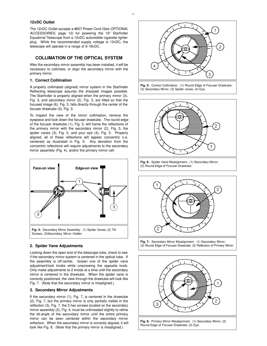
To inspect the view of the mirror collimation, remove the eyepiece and look down the focuser drawtube. The round edge of the focuser drawtube (1), Fig. 5, will frame the reflections of the primary mirror with the secondary mirror (2), Fig. 5, the spider vanes (3), Fig. 5, and your eye (4), Fig. 5. Properly aligned, all of these reflections will appear concentric (i.e. centered) as illustrated in Fig. 5. Any deviation from the concentric reflections will require adjustments to the secondary mirror assembly (Fig. 4), and/or the primary mirror cell.
Fig. 5: Correct Collimation. (1) Round Edge of Focuser Drawtube;
(2) Secondary Mirror; (3) Spider vanes; (4) Eye.
| Fig. 6: Spider Vane Misalignment. (1) Secondary Mirror; |
(2) Round Edge of Focuser Drawtube. | |
1
3 |
|
2 |
|
Fig. 4: Secondary Mirror Assembly. (1) Spider Vanes; (2) Tilt |
|
Screws; (3)Secondary Mirror Holder. |
|
| Fig. 7: Secondary Mirror Misalignment. (1) Secondary Mirror; |
2. Spider Vane Adjustments | (2) Round Edge of Focuser Drawtube; (3) Reflection of Primary Mirror. |
Looking down the open end of the telescope tube, check to see if the secondary mirror system is centered in the optical tube. If the assembly is
3. Secondary Mirror Adjustments
If the secondary mirror (1), Fig. 7, is centered in the drawtube (2), Fig. 7, but the primary mirror is only partially visible in the reflection (3), Fig. 7, the 3 hex screws located on the secondary mirror assembly (2), Fig. 4, must be unthreaded slightly to refine the