- 5 -
Fig. 1; this should prevent rotation of the telescope about the declination axis.
BALANCING THE TELESCOPE
The telescope must be balanced around both axes in order for the mount to track accurately, keeping an object within the telescope's field of view. Most tracking errors are the result of improper balancing. With an improperly balanced telescope objects may become difficult to find or, once found, may be easily lost. To balance the telescope:
1.Loosen the declination lock knob (7), Fig 1.
2.Rotate the telescope about both axes so that the declination shaft (10), Fig 1, and the optical tube (4), Fig 1, are both horizontal in relationship to the ground.
3.Loosen the counterweight lock knobs and slide the counterweights along the declination shaft, as necessary, until the telescope is balanced about the polar axis (5), Fig. 1. Lock the counterweights in place and make certain that the counterweight safety washer (11), Fig 1, is firmly in place.
4.Loosen the mounting straps (23), Fig 1, just enough to allow the optical tube to slide within the straps.
5.Slide the tube back and forth within the straps until the telescope is in balance about the declination axis. Tighten the mounting straps (23), Fig 1.
6.
7.Small scribe marks may be placed on the Declination shaft and optical tube to indicate the correct balancing positions. Such scribing will be an advantage if the telescope is to be frequently disassembled or transported.
CONTROL PANEL
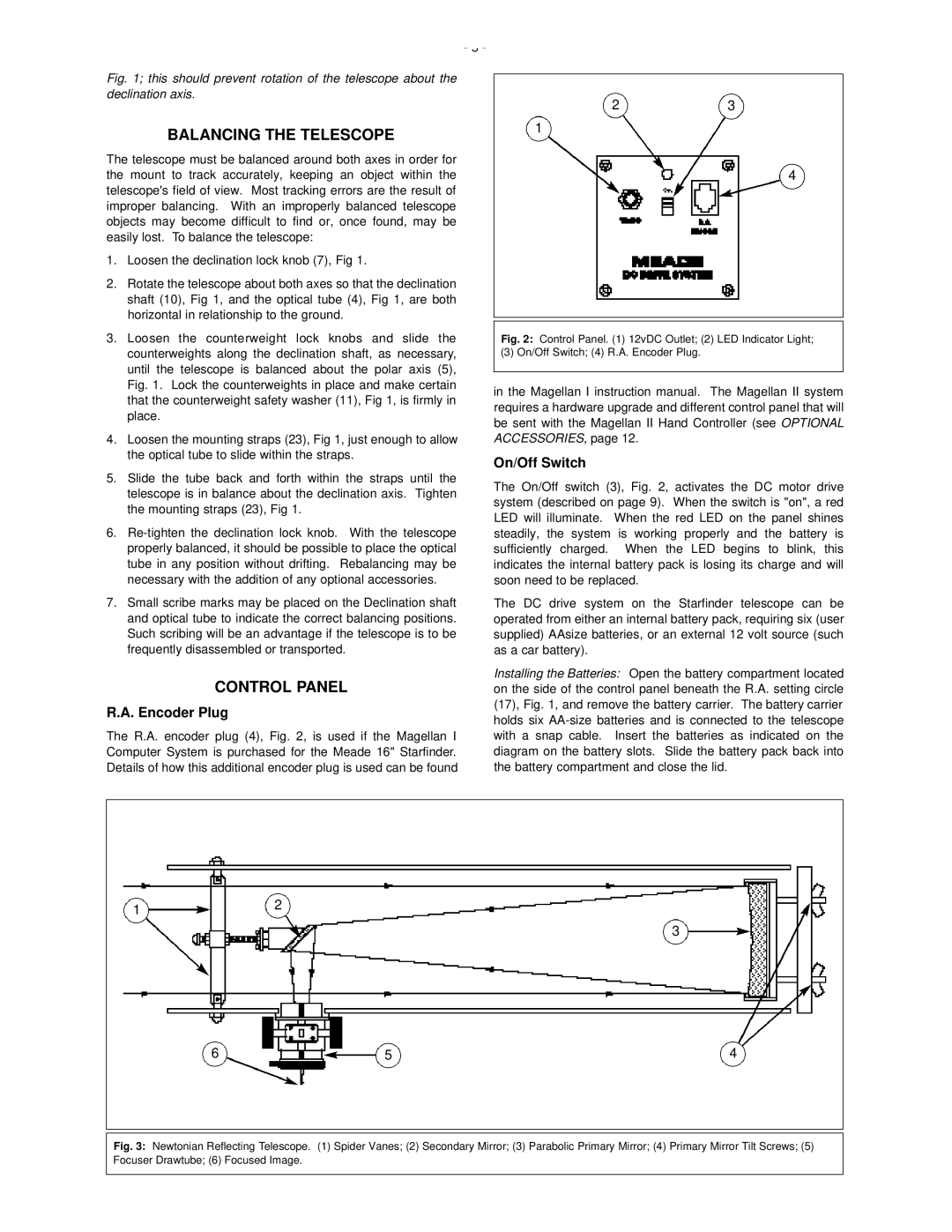
R.A. Encoder Plug
The R.A. encoder plug (4), Fig. 2, is used if the Magellan I Computer System is purchased for the Meade 16" Starfinder. Details of how this additional encoder plug is used can be found
23
1
4
Fig. 2: Control Panel. (1) 12vDC Outlet; (2) LED Indicator Light;
(3) On/Off Switch; (4) R.A. Encoder Plug.
in the Magellan I instruction manual. The Magellan II system requires a hardware upgrade and different control panel that will be sent with the Magellan II Hand Controller (see OPTIONAL ACCESSORIES, page 12.
On/Off Switch
The On/Off switch (3), Fig. 2, activates the DC motor drive system (described on page 9). When the switch is "on", a red LED will illuminate. When the red LED on the panel shines steadily, the system is working properly and the battery is sufficiently charged. When the LED begins to blink, this indicates the internal battery pack is losing its charge and will soon need to be replaced.
The DC drive system on the Starfinder telescope can be operated from either an internal battery pack, requiring six (user supplied) AAsize batteries, or an external 12 volt source (such as a car battery).
Installing the Batteries: Open the battery compartment located on the side of the control panel beneath the R.A. setting circle (17), Fig. 1, and remove the battery carrier. The battery carrier holds six
12
3
6 | 5 | 4 |