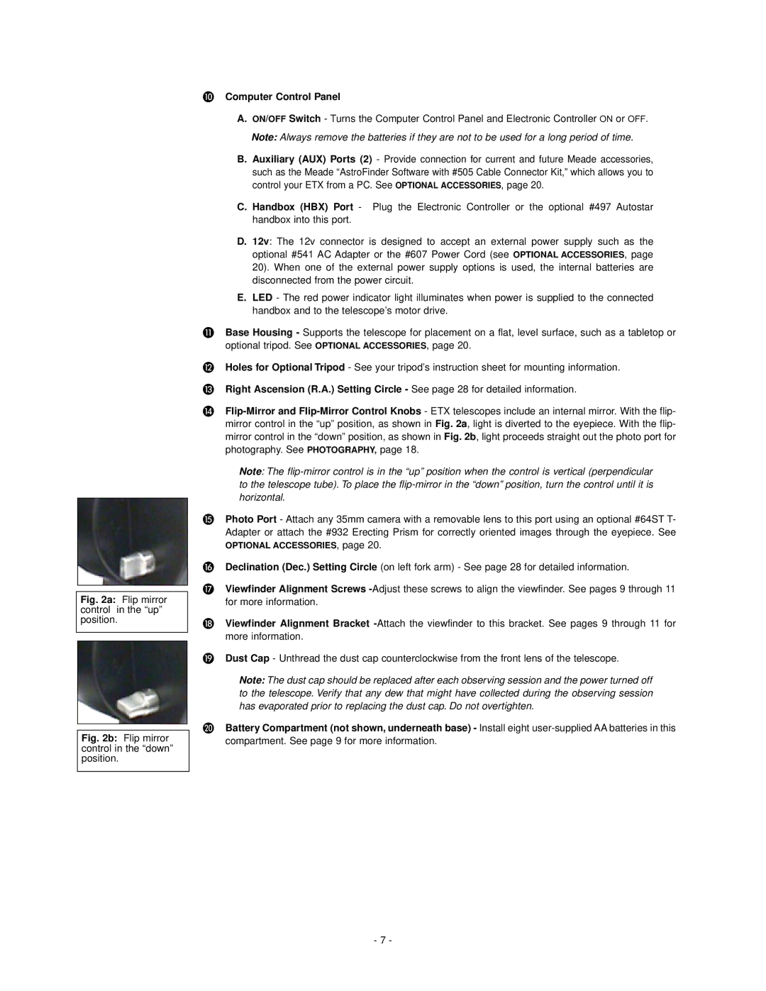
Fig. 2a: Flip mirror control in the “up” position.
Fig. 2b: Flip mirror control in the “down” position.
Computer Control Panel
A.ON/OFF Switch - Turns the Computer Control Panel and Electronic Controller ON or OFF.
Note: Always remove the batteries if they are not to be used for a long period of time.
B.Auxiliary (AUX) Ports (2) - Provide connection for current and future Meade accessories, such as the Meade “AstroFinder Software with #505 Cable Connector Kit,” which allows you to control your ETX from a PC. See OPTIONAL ACCESSORIES, page 20.
C.Handbox (HBX) Port - Plug the Electronic Controller or the optional #497 Autostar handbox into this port.
D.12v: The 12v connector is designed to accept an external power supply such as the optional #541 AC Adapter or the #607 Power Cord (see OPTIONAL ACCESSORIES, page 20). When one of the external power supply options is used, the internal batteries are disconnected from the power circuit.
E.LED - The red power indicator light illuminates when power is supplied to the connected handbox and to the telescope’s motor drive.
Base Housing - Supports the telescope for placement on a flat, level surface, such as a tabletop or optional tripod. See OPTIONAL ACCESSORIES, page 20.
Holes for Optional Tripod - See your tripod’s instruction sheet for mounting information.
Right Ascension (R.A.) Setting Circle - See page 28 for detailed information.
Note: The
Photo Port - Attach any 35mm camera with a removable lens to this port using an optional #64ST T- Adapter or attach the #932 Erecting Prism for correctly oriented images through the eyepiece. See OPTIONAL ACCESSORIES, page 20.
Declination (Dec.) Setting Circle (on left fork arm) - See page 28 for detailed information. Viewfinder Alignment Screws
for more information.
Viewfinder Alignment Bracket
more information.
Dust Cap - Unthread the dust cap counterclockwise from the front lens of the telescope.
Note: The dust cap should be replaced after each observing session and the power turned off to the telescope. Verify that any dew that might have collected during the observing session has evaporated prior to replacing the dust cap. Do not overtighten.
Battery Compartment (not shown, underneath base) - Install eight
compartment. See page 9 for more information.
- 7 -