12
Step 9
Shroud Assembly
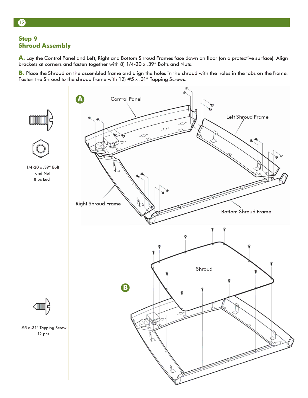
A. Lay the Control Panel and Left, Right and Bottom Shroud Frames face down on floor (on a protective surface). Align brackets at corners and fasten together with 8)
B. Place the Shroud on the assembled frame and align the holes in the shroud with the holes in the tabs on the frame. Fasten the Shroud to the shroud frame with 12) #5 x .31” Tapping Screws.
and Nut
8 pc Each
A | Control Panel |
Left Shroud Frame
Right Shroud Frame
Bottom Shroud Frame
Shroud
B
#5 x .31” Tapping Screw
12 pcs.
