16
Step 16
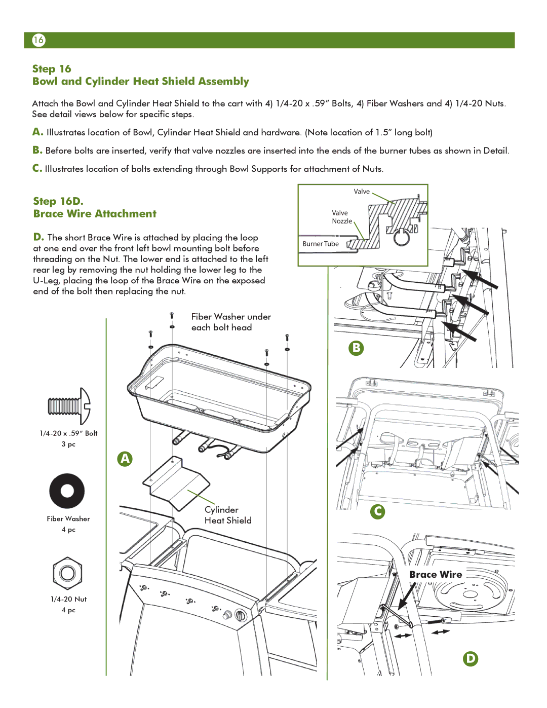
Bowl and Cylinder Heat Shield Assembly
Attach the Bowl and Cylinder Heat Shield to the cart with 4)
A. Illustrates location of Bowl, Cylinder Heat Shield and hardware. (Note location of 1.5” long bolt)
B. Before bolts are inserted, verify that valve nozzles are inserted into the ends of the burner tubes as shown in Detail. C. Illustrates location of bolts extending through Bowl Supports for attachment of Nuts.
Step 16D.
Brace Wire Attachment
D. The short Brace Wire is attached by placing the loop at one end over the front left bowl mounting bolt before threading on the Nut. The lower end is attached to the left rear leg by removing the nut holding the lower leg to the
Valve
Valve
Nozzle
Burner Tube
3 pc
Fiber Washer
4 pc
Fiber Washer under each bolt head
A
Cylinder
Heat Shield
B
C
Brace Wire
4 pc
D