SR-10K, SR-10K Mag-Stripe Access System specifications
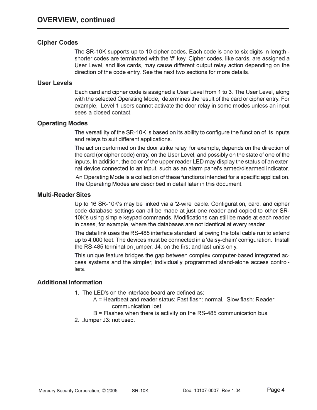
The Mercury SR-10K Mag-Stripe Access System is a cutting-edge access control solution designed for environments that require robust security and reliable performance. This system is well-suited for various applications, including commercial buildings, educational institutions, and industrial facilities. With its advanced technology and user-friendly design, the SR-10K provides a comprehensive security platform that streamlines access management.One of the main features of the SR-10K is its compatibility with both magnetic stripe cards and ISO 7810-compliant cards. This flexibility allows organizations to implement existing card technologies without the need for extensive infrastructure changes. The system supports both single-door and multi-door configurations, making it adaptable to different facility requirements.
The SR-10K includes a powerful embedded controller that ensures efficient processing of access control transactions. This controller leverages smart technology to manage access rights and monitor activities in real-time, providing operators with immediate insights into system status. Additionally, it incorporates a user-friendly interface, allowing for straightforward programming and administration of the access control system.
Durability is a key characteristic of the SR-10K, as it is designed to withstand the rigors of everyday use in demanding environments. The system features weather-resistant components, making it suitable for both indoor and outdoor installations. This robustness contributes to the overall reliability of the security solution, reducing maintenance and operational costs over time.
The SR-10K also integrates seamlessly with existing security infrastructures, supporting various communication protocols such as Wiegand and RS-485. This connectivity allows organizations to enhance their security measures by integrating the access control system with surveillance cameras, alarms, and other security devices. The SR-10K can be easily scaled to accommodate future growth, ensuring that the system remains effective as security needs evolve.
In addition to its technical features, the SR-10K prioritizes user experience. The system offers intuitive software for system management, which simplifies the process of managing user profiles, access permissions, and activity logs. This accessibility ensures that security personnel can effectively monitor and respond to access events.
Overall, the Mercury SR-10K Mag-Stripe Access System stands out as a versatile and reliable access control solution. Its combination of advanced features, robust construction, and ease of use makes it an ideal choice for organizations seeking to enhance their security while maintaining operational efficiency.
