Scanner Parts
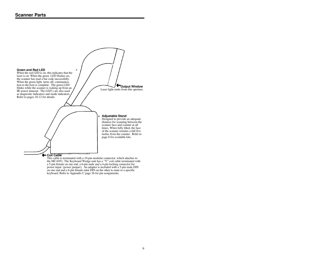
Green and Red LED | º |
When the red LED is on, this indicates that the | |
laser is on. When the green LED flashes on, |
|
the scanner has read a bar code successfully. |
|
When the green light turns off, communica- |
|
tion to the host is complete. The green LED |
|
blinks while the scanner is waking up from an |
|
IR sensor timeout. The LED’s are also used |
|
as diagnostic indicators and mode indicators. |
|
Refer to pages |
|
![]() Output Window Laser light emits from this aperture.
Output Window Laser light emits from this aperture.
»Adjustable Stand
Designed to provide an adequate distance for scanning between the scanner face and counter at all times. When fully tilted, the face of the scanner remains a full five inches from the counter. Refer to page 8 for available kits.
 Coil Cable
This cable is terminated with a
9