Manuals
/
Meyer
/
Household Appliance
/
Furnace
Meyer
2900, 526, 4000
manual
Electrical Hookup Figure, Install Circulating Blower And Filter
Models:
2900
4000
526
1
25
36
36
Download
36 pages
11.61 Kb
22
23
24
25
26
27
28
29
Troubleshooting
Specs
Install
Repair Parts
46-2900-8Wiring Diagram
Warranty
Maintenance
Problem
Woodchuck Final Assembly
Safety
Page 25
Image 25
Page 24
Page 26
Page 25
Image 25
Page 24
Page 26
Contents
MODELS
INSTRUCTION AND PARTS BOOK FOR
Phone 715/654-5132 Fax 715/654-5513
07/97
TRANSPORTATION DAMAGES
INTRODUCTION
TABLE OF CONTENTS
DANGER
FURNACE SAFETY
DANGER
DANGER
MODEL
SPECIFICATIONS
DISCLAIMER NOTICE
MODEL
HIGH QUALITY CONSTRUCTION
GENERAL INFORMATION
EFFICIENCY
COMFORT
FIGURE FIGURE
ADDITION COMFORT AND SAVING
OPERATION
OPERATION PROCEDURE IN THE EVENT OF POWER FAILURE
COMMON SENSE
IF YOU HAVE CHIMNEY FIRE
BURNING WOOD IN YOUR WOOD- CHUCK
OPERATING YOUR WOODCHUCK FURNACE
STARTUP
FIGURE 5 WOODCHUCK CONTROLS
HELPFUL HINTS
ASH REMOVAL
STARTING A COAL FIRE
BURNING COAL IN YOUR WOOD- CHUCK
RECHARGING
BANKING
OPTIONAL CATALYTIC COMBUSTOR FOR MODELS 2900/4000
MAINTENANCE
ASH REMOVAL
PROBLEM
TROUBLE SHOOTING
SOLUTION
POSSIBLE CAUSE
SOLUTION
PROBLEM
POSSIBLE CAUSE
9. Excessive amounts of
PLACEMENT AND MINIMUM CLEAR ANCES
INSTALLATION
GENERAL REQUIREMENTS
FIGURE 7 LOCATING THE WOODCHUCK
FIGURE 8 TYPICAL CHIMNEY CHECKLIST
TYPICAL STOVE PIPE INSTALLATION
CHIMNEY INSTALLATION
FIGURE 9 CHIMNEY/ROOF CLEARANCE
STOVE PIPE INSTALLATION
INSTALLING YOUR WOODCHUCK
INSTALLATION OF A BAROMETRIC DRAFT
DAMPERS IN STOVE PIPES
ADD-ONINSTALLATIONS
AIR DUCT INSTALLATION
OPTIONAL SHAKER GRATE INSTALLATION FOR MODEL
WOODCHUCK FINAL ASSEMBLY
FIGURE 12 PARALLEL ADD-ONINSTALLATION
FIGURE 13 CENTRAL ADD-ONINSTALLATION
FIGURE 14 POOR INSTALLATIONS
INSTALL SHAKER GRATE HANDLE MODEL 2900 ONLY
FIGURE 15 INSTALL SHAKER GRATE HANDLE
FIGURE 16 INSTALL OPTIONAL SHAKER GRATE FOR MODEL
INSTALL FIREBRICK
FIGURE 17 INSTALL FIREBRICK
ASSEMBLE MANUAL DRAFT MODEL 526 ONLY
FIGURE 19 INSTALL MANUAL DRAFT-MODEL526
INSTALL FILTER BOX
INSTALL CIRCULATING BLOWER
FEED
MOTOR
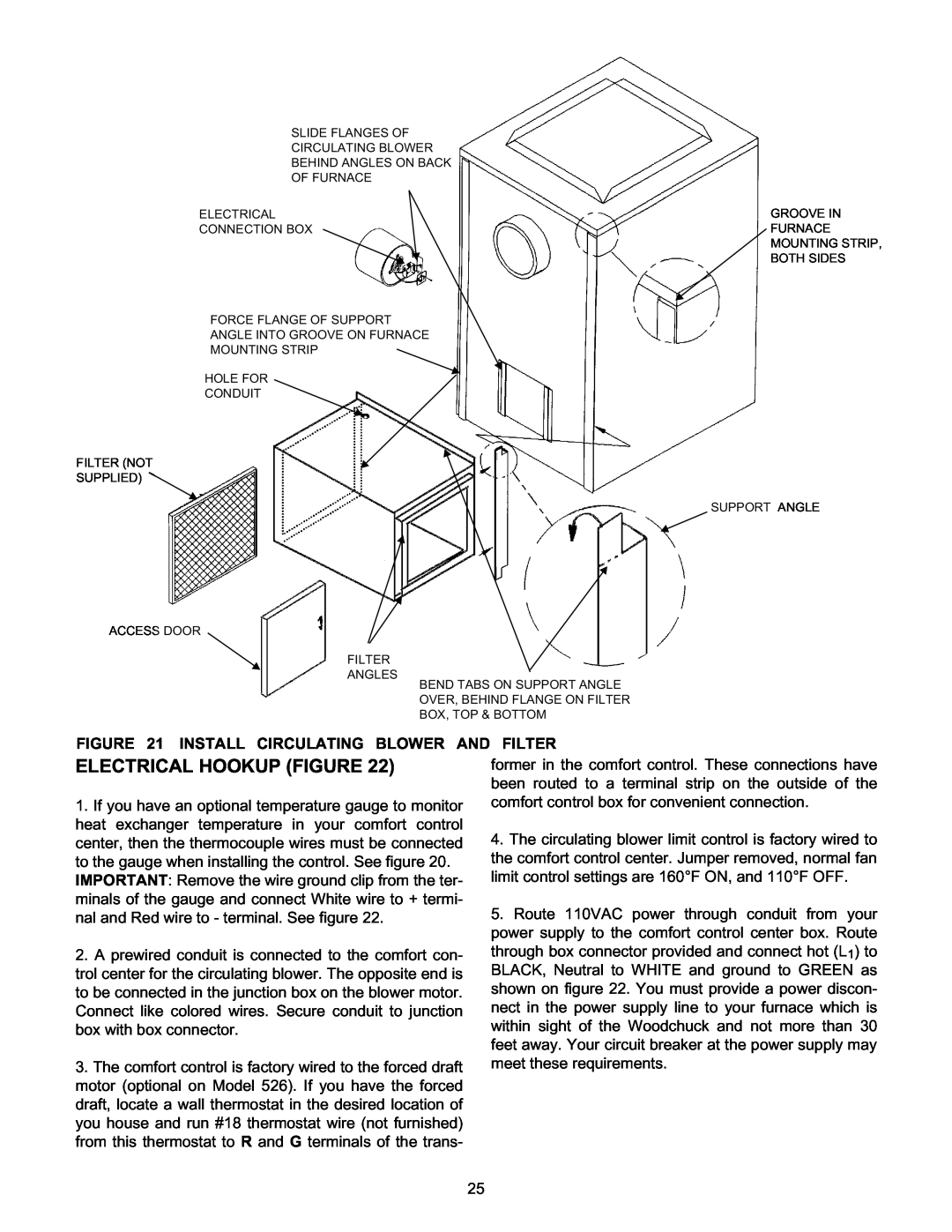
ELECTRICAL HOOKUP FIGURE
FIGURE 21 INSTALL CIRCULATING BLOWER AND FILTER
FIGURE 22 ELECTRICAL WIRING DIAGRAM
BASIC UNIT FOR MODEL
REPAIR PARTS
KEY NO. PART NO
DESCRIPTION
KEY NO. PART NO
BASIC UNIT FOR MODEL
DESCRIPTION
KEY NO. PART NO
KEY NO. PART NO
BASIC UNIT FOR MODEL
DESCRIPTION
KEY NO. PART NO
#05-2900SHAKER GRATE FOR MODELS 2900/4000
#05-5260-OPTIONALSHAKER GRATE FOR MODEL
FILTER BOX
2900/4000
#08-0090COMPLETE BLOWER ASSY
CIRCULATING BLOWER #08-0100 COMFORT CONTROL
DESCRIPTION
KEY NO. PART NO. DESCRIPTION
46-2900-8Wiring Diagram
PERSONAL DATA INFORMATION FOR FUTURE REFERENCE
This Page Intentionally Blank
LIMITED WARRANTY
MEYER MANUFACTURING CORPORATION P.O. Box
Manufactured By
Dorchester, Wisconsin
Dorchester, Wisconsin
Top
Page
Image
Contents