Manuals
/
MGE UPS Systems
/
Computer Equipment
/
Power Supply
MGE UPS Systems
1500C
user manual
Pulsar, EXtreme CLA
Models:
1500C
1
1
30
30
Download
30 pages
22.04 Kb
1
2
3
4
5
6
7
8
Troubleshooting
Technical characteristics
Install
Maintenance
Battery connection
End of backup time
Special precautions
Using this document
Page 1
Image 1
www.mgeups.com
MGE
UPS
SYSTEMS
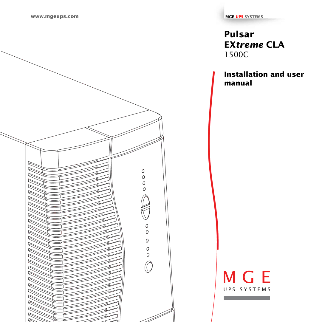
Pulsar
EX
treme
CLA
1500C
Installation and user manual
Page 1
Page 2
Page 1
Image 1
Page 1
Page 2
Contents
EXtreme CLA
Pulsar
Introduction
Safety rules
Safety
Safety of persons
Product safety
Foreword
Using this document
Pictograms
Contents
Maintenance
Pulsar EXtreme range
Presentation
Tower model
Rack model
Back
Presentation
Control panel
Alarms Battery Ê Ê Ê Ê Ê Load Remaining
Unpacking and checks
Installation
2526
12 51031998EN/AA
Installation of the rack version
Connection to the RS 232 or USB communications port optional
Installation of the communications-card option
Connecting the battery configuration to the UPS
Battery connection
Curve C Max Cable and circuit-breaker not supplied 140
Curve C Max Cable and circuit-breaker not provided 140
UPS connection and settings Tower model Rack model
Start-up
Operation
Bargraph indications
All connected equipment is energised
Threshold for the low-battery warning
Transfer to battery power
End of backup time
Equipment connected to the UPS is supplied by the battery
Personalisable function Default setting Options
Battery tab
Personalisation optional
Function
Output tab
Connected equipment is no longer supplied with power
Bypass tab
Troubleshooting
Maintenance
Indication Signification
Correction
Indication Signification Correction
Environment
UPS recycling at the end of service life
Simplified diagram Operating conditions
Technical characteristics
Appendices
Input voltage and frequency Output voltage and frequency
UPS on / OFF via software
Glossary
Connection
Index
5103199800-AA
Top
Page
Image
Contents