ENGLISH
SECTION 2 - INSTALLATION
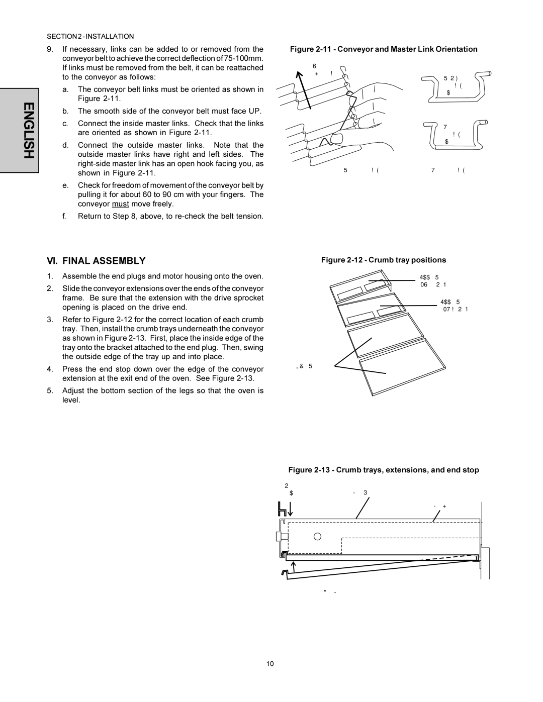
9.If necessary, links can be added to or removed from the conveyor belt to achieve the correct deflection of
a.The conveyor belt links must be oriented as shown in Figure
b.The smooth side of the conveyor belt must face UP.
c.Connect the inside master links. Check that the links are oriented as shown in Figure
d.Connect the outside master links. Note that the outside master links have right and left sides. The
e.Check for freedom of movement of the conveyor belt by pulling it for about 60 to 90 cm with your fingers. The conveyor must move freely.
f.Return to Step 8, above, to
Figure 2-11 - Conveyor and Master Link Orientation
Direction
of travel
CORRECT master link position
Incorrect
master link
position
Outside master link | Inside master link |
orientation | orientation |
VI. FINAL ASSEMBLY
1.Assemble the end plugs and motor housing onto the oven.
2.Slide the conveyor extensions over the ends of the conveyor frame. Be sure that the extension with the drive sprocket opening is placed on the drive end.
3.Refer to Figure
4.Press the end stop down over the edge of the conveyor extension at the exit end of the oven. See Figure
5.Adjust the bottom section of the legs so that the oven is level.
Figure 2-12 - Crumb tray positions
Upper Oven
(Drive End)
Upper Oven
(Idler End)
Lower Oven
Figure 2-13 - Crumb trays, extensions, and end stop
End |
|
stop | Conveyor extension |
Conveyor frame
Crumb tray
10