SECTION 2 - INSTALLATION
ENGLISH
III. ASSEMBLY
A.Caster Removal
After moving the ovens in to the installation location, remove the casters attached to each oven cavity. These casters are provided for
B.Stacking
If the installation will include upper ovens mounted atop lower ovens, stack the oven cavities.
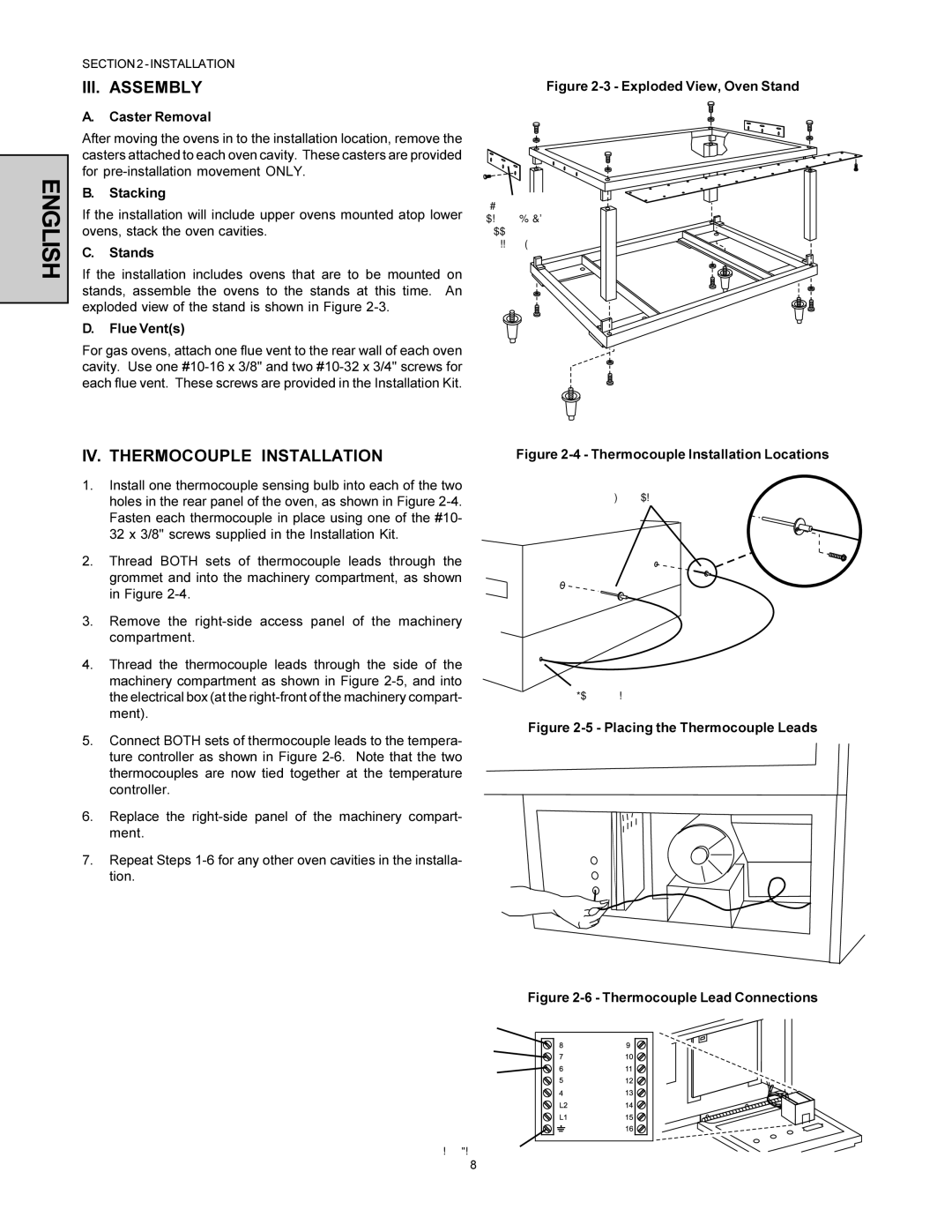
C.Stands
If the installation includes ovens that are to be mounted on stands, assemble the ovens to the stands at this time. An exploded view of the stand is shown in Figure
D.Flue Vent(s)
For gas ovens, attach one flue vent to the rear wall of each oven cavity. Use one
IV. THERMOCOUPLE INSTALLATION
1.Install one thermocouple sensing bulb into each of the two holes in the rear panel of the oven, as shown in Figure
2.Thread BOTH sets of thermocouple leads through the grommet and into the machinery compartment, as shown in Figure
3.Remove the
4.Thread the thermocouple leads through the side of the machinery compartment as shown in Figure
5.Connect BOTH sets of thermocouple leads to the tempera- ture controller as shown in Figure
6.Replace the
7.Repeat Steps
Figure 2-3 - Exploded View, Oven Stand
Attachment
plates inc. w/
upper oven
installation kit
Figure 2-4 - Thermocouple Installation Locations
Thermocouples
Figure 2-5 - Placing the Thermocouple Leads
Figure 2-6 - Thermocouple Lead Connections
8=White=Positive
7=Red=Negative R=No Connection
Ground=Shielded cable
8