V. CONVEYOR INSTALLATION
NOTE
Split belt conveyors can only be installed from the end of the oven with the drive motor.
To remove the drive sprocket (if necessary), loosen the set screw on the conveyor collar as shown in Figure
1.Lift the conveyor and position it in the oven as shown in Figure
SECTION 2 - INSTALLATION
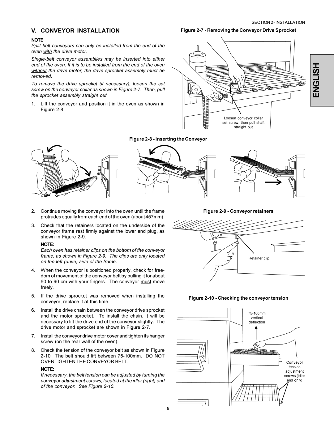
Figure 2-7 - Removing the Conveyor Drive Sprocket


 ENGLISH
Loosen conveyor collar set screw, then pull shaft straight out
Figure 2-8 - Inserting the Conveyor
2.Continue moving the conveyor into the oven until the frame protrudes equally from each end of the oven (about 457mm).
3.Check that the retainers located on the underside of the conveyor frame rest firmly against the lower end plug, as shown in Figure
NOTE:
Each oven has retainer clips on the bottom of the conveyor frame, as shown in Figure
4.When the conveyor is positioned properly, check for free- dom of movement of the conveyor belt by pulling it for about 60 to 90 cm with your fingers. The conveyor must move freely.
5.If the drive sprocket was removed when installing the conveyor, replace it at this time.
6.Install the drive chain between the conveyor drive sprocket and the motor sprocket. To install the chain, it will be necessary to lift the drive end of the conveyor slightly. The drive motor and sprocket are shown in Figure
7.Install the conveyor drive motor cover and tighten its hanger screw (on the rear wall of the oven).
8.Check the tension of the conveyor belt as shown in Figure
NOTE:
If necessary, the belt tension can be adjusted by turning the conveyor adjustment screws, located at the idler (right) end of the conveyor. See Figure
Figure 2-9 - Conveyor retainers
Retainer clip
Figure 2-10 - Checking the conveyor tension
vertical
deflection
Conveyor
tension
adjustment
screws (idler
end only)
9