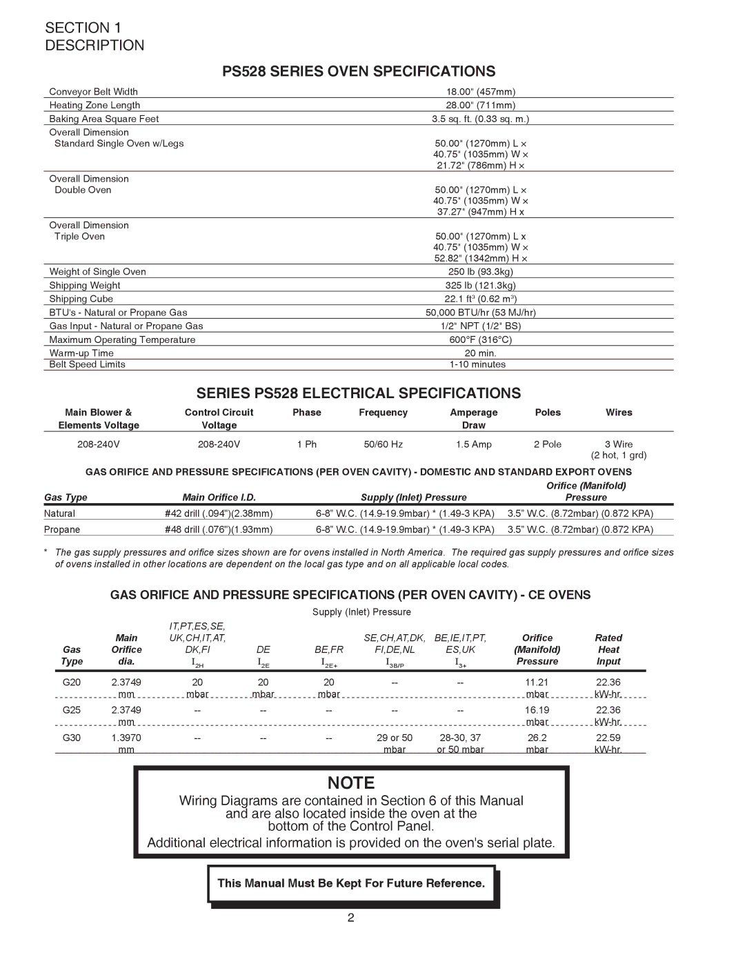
PS528G specifications
The Middleby Marshall PS528G is a cutting-edge gas-fired conveyor oven, designed to revolutionize the way food is cooked in high-demand commercial kitchen environments. Renowned for its exceptional performance, this oven combines advanced technology with user-friendly features, making it a preferred choice for restaurants, pizzerias, and other food service operations.One of the standout features of the PS528G is its impressive cooking capacity. With a spacious cooking chamber and a conveyor belt that ensures uniform movement of food items, this oven can handle a variety of menu items all at once. This is particularly beneficial for establishments with high volume requirements, as the efficient design allows for consistent results and quick turnaround times.
The PS528G utilizes advanced jet air technology, which circulates hot air throughout the cooking chamber. This ensures even cooking and browning of food, eliminating cold spots and ensuring that every item comes out perfectly cooked. The enhanced air flow not only improves cooking quality but also reduces the cooking time compared to traditional ovens.
Energy efficiency is another highlight of the Middleby Marshall PS528G. The gas-fired system is engineered to optimize fuel consumption, making it both environmentally friendly and cost-effective. Operators can expect significantly lower energy bills without compromising on cooking performance, making this oven an ideal investment for busy kitchens.
Moreover, the PS528G features a user-friendly digital control panel. This intuitive interface allows operators to easily set cooking temperatures, adjust conveyor speeds, and monitor cooking cycles with precision. The programmable features enable users to save recipes, ensuring consistency across batches and streamlining kitchen operations.
Safety is also a top priority with the PS528G. The oven is equipped with safety features such as a reliable ignition system and temperature controls that prevent overheating, reducing the risk of accidents in busy kitchens.
In conclusion, the Middleby Marshall PS528G is a powerhouse in the realm of commercial cooking. Its combination of high cooking capacity, advanced jet air technology, energy efficiency, user-friendly controls, and safety features make it an essential tool for any food service operation that demands high-quality cooking in a fast-paced environment. As the culinary landscape continues to evolve, the PS528G stands as a testament to innovation and reliability in the kitchen.