INSTALLATION
Optionally Install Backbone Uplink Adapter
WARNING: Remove AC line cord from power source before installing backbone uplink adaptor in
CAUTION: Wear a grounding device and observe electrostatic discharge precautions when installing backbone uplink adaptor in the
To install the backbone uplink adapter in the
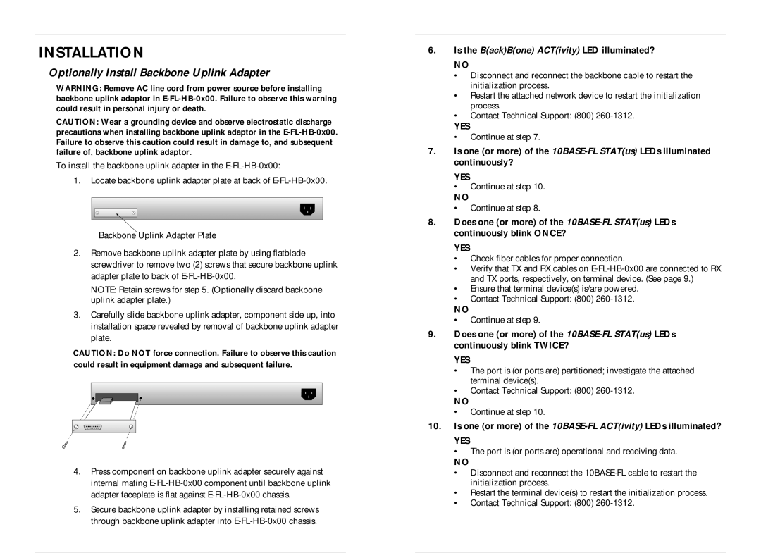
1.Locate backbone uplink adapter plate at back of
Backbone Uplink Adapter Plate
2.Remove backbone uplink adapter plate by using flatblade screwdriver to remove two (2) screws that secure backbone uplink adapter plate to back of
NOTE: Retain screws for step 5. (Optionally discard backbone uplink adapter plate.)
3.Carefully slide backbone uplink adapter, component side up, into installation space revealed by removal of backbone uplink adapter plate.
CAUTION: Do NOT force connection. Failure to observe this caution could result in equipment damage and subsequent failure.
4.Press component on backbone uplink adapter securely against internal mating
5.Secure backbone uplink adapter by installing retained screws through backbone uplink adapter into
6.Is the B(ack)B(one) ACT(ivity) LED illuminated?
NO
•Disconnect and reconnect the backbone cable to restart the initialization process.
•Restart the attached network device to restart the initialization process.
•Contact Technical Support: (800)
YES
•Continue at step 7.
7.Is one (or more) of the
YES
•Continue at step 10.
NO
•Continue at step 8.
8.Does one (or more) of the
YES
•Check fiber cables for proper connection.
•Verify that TX and RX cables on
•Ensure that terminal device(s) is/are powered.
•Contact Technical Support: (800)
NO
•Continue at step 9.
9.Does one (or more) of the
YES
•The port is (or ports are) partitioned; investigate the attached terminal device(s).
•Contact Technical Support: (800)
NO
•Continue at step 10.
10.Is one (or more) of the
YES
•The port is (or ports are) operational and receiving data.
NO
•Disconnect and reconnect the
•Restart the terminal device(s) to restart the initialization process.
•Contact Technical Support: (800)