1 Introduction
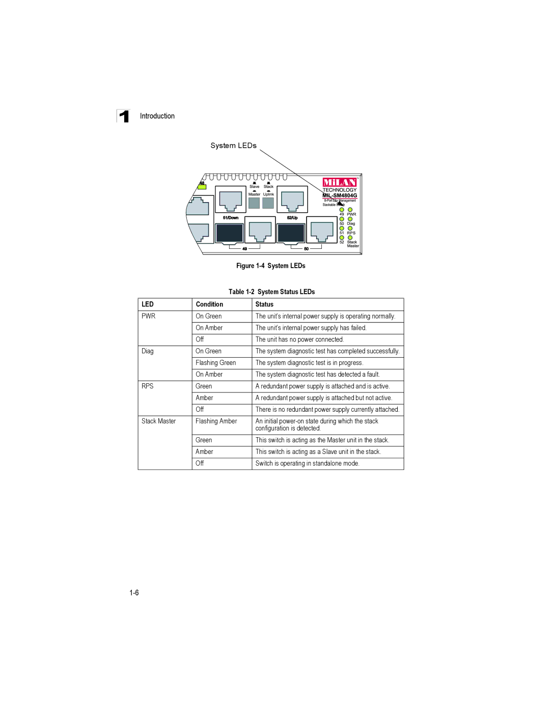
System LEDs
| Figure | |
| Table | |
|
|
|
LED | Condition | Status |
|
|
|
PWR | On Green | The unit’s internal power supply is operating normally. |
|
|
|
| On Amber | The unit’s internal power supply has failed. |
|
|
|
| Off | The unit has no power connected. |
|
|
|
Diag | On Green | The system diagnostic test has completed successfully. |
|
|
|
| Flashing Green | The system diagnostic test is in progress. |
|
|
|
| On Amber | The system diagnostic test has detected a fault. |
|
|
|
RPS | Green | A redundant power supply is attached and is active. |
|
|
|
| Amber | A redundant power supply is attached but not active. |
|
|
|
| Off | There is no redundant power supply currently attached. |
|
|
|
Stack Master | Flashing Amber | An initial |
|
| configuration is detected. |
| Green | This switch is acting as the Master unit in the stack. |
|
|
|
| Amber | This switch is acting as a Slave unit in the stack. |
|
|
|
| Off | Switch is operating in standalone mode. |
|
|
|
