Twisted-Pair Cable and Pin Assignments B
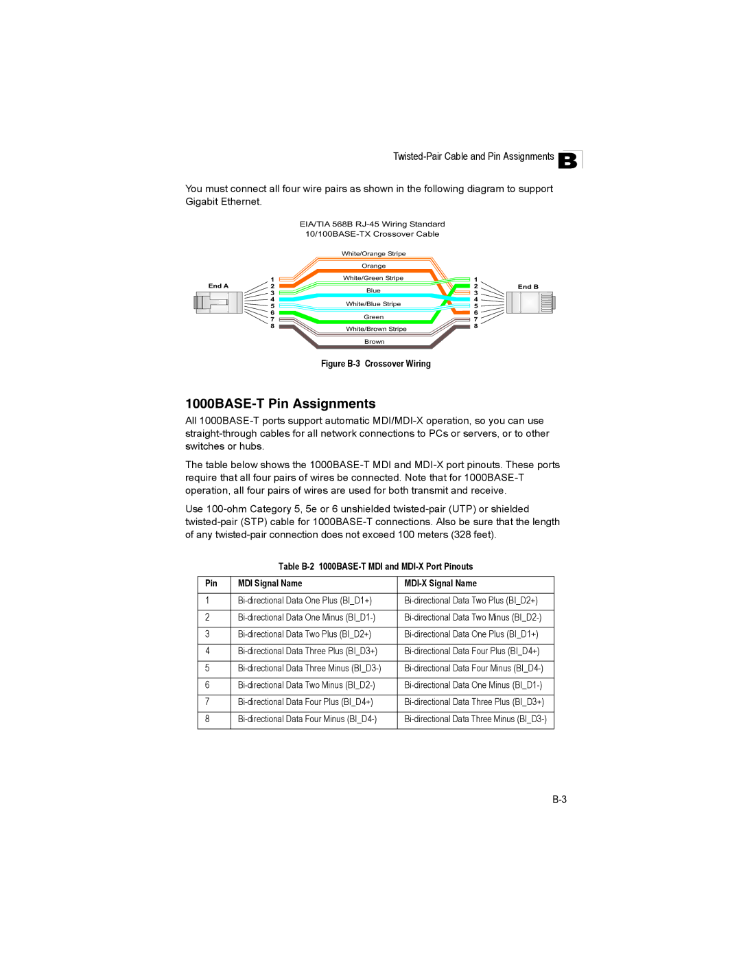
You must connect all four wire pairs as shown in the following diagram to support Gigabit Ethernet.
EIA/TIA 568B RJ-45 Wiring Standard 10/100BASE-TX Crossover Cable
White/Orange Stripe
| | Orange | | |
| 1 | White/Green Stripe | 1 | |
End A | 2 | Blue | 2 | End B |
| 3 | 3 | |
| 4 | | 4 | |
| 5 | White/Blue Stripe | 5 | |
| 6 | Green | 6 | |
| 7 | 7 | |
| 8 | White/Brown Stripe | 8 | |
| | | |
Brown
Figure B-3 Crossover Wiring
1000BASE-T Pin Assignments
All 1000BASE-T ports support automatic MDI/MDI-X operation, so you can use straight-through cables for all network connections to PCs or servers, or to other switches or hubs.
The table below shows the 1000BASE-T MDI and MDI-X port pinouts. These ports require that all four pairs of wires be connected. Note that for 1000BASE-T operation, all four pairs of wires are used for both transmit and receive.
Use 100-ohm Category 5, 5e or 6 unshielded twisted-pair (UTP) or shielded twisted-pair (STP) cable for 1000BASE-T connections. Also be sure that the length of any twisted-pair connection does not exceed 100 meters (328 feet).
Table B-2 1000BASE-T MDI and MDI-X Port Pinouts
Pin | MDI Signal Name | MDI-X Signal Name |
| | |
1 | Bi-directional Data One Plus (BI_D1+) | Bi-directional Data Two Plus (BI_D2+) |
| | |
2 | Bi-directional Data One Minus (BI_D1-) | Bi-directional Data Two Minus (BI_D2-) |
| | |
3 | Bi-directional Data Two Plus (BI_D2+) | Bi-directional Data One Plus (BI_D1+) |
| | |
4 | Bi-directional Data Three Plus (BI_D3+) | Bi-directional Data Four Plus (BI_D4+) |
| | |
5 | Bi-directional Data Three Minus (BI_D3-) | Bi-directional Data Four Minus (BI_D4-) |
| | |
6 | Bi-directional Data Two Minus (BI_D2-) | Bi-directional Data One Minus (BI_D1-) |
| | |
7 | Bi-directional Data Four Plus (BI_D4+) | Bi-directional Data Three Plus (BI_D3+) |
| | |
8 | Bi-directional Data Four Minus (BI_D4-) | Bi-directional Data Three Minus (BI_D3-) |
| | |

