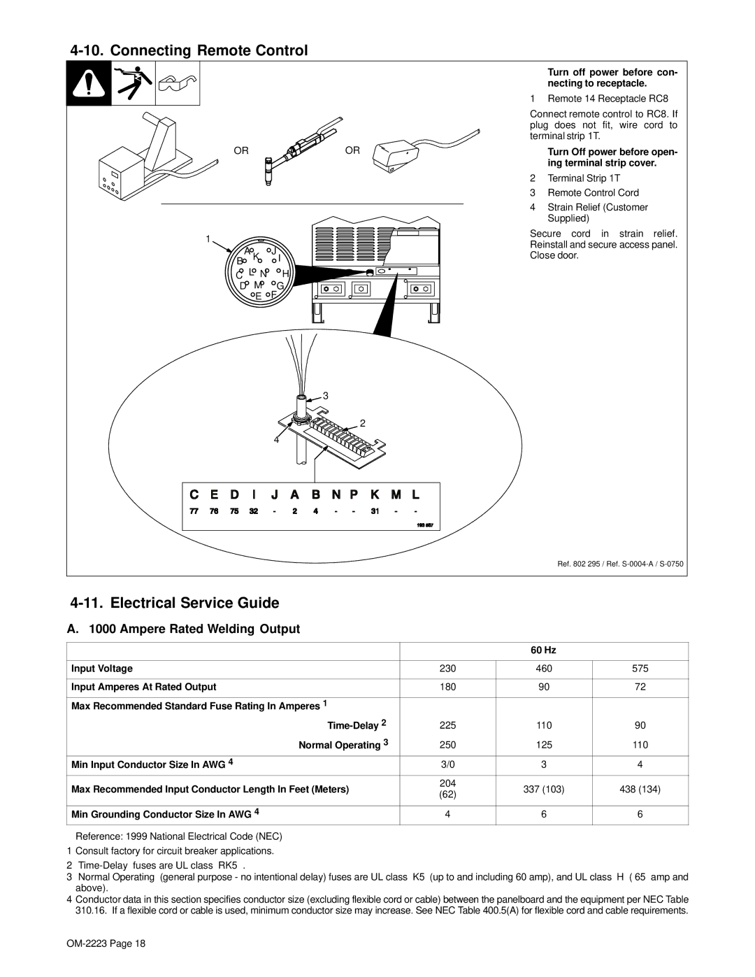
1250, 1000 specifications
Miller Electric is a renowned name in the welding and fabrication industry, providing high-quality machines and equipment that cater to a range of applications. Among its impressive line of products are the Miller Electric 1000 and 1250 arc welding machines, designed to offer exceptional performance in both industrial and commercial environments.One of the main features of the Miller Electric 1000 model is its robust construction, making it ideal for heavy-duty welding tasks. It boasts a powerful output that provides a significant range of welding power, accommodating various electrode sizes and types. This flexibility allows for effective use in a variety of welding processes, including Stick, TIG, and MIG, ensuring that users can tackle a wide array of jobs without needing multiple machines.
The Miller Electric 1250 takes things a step further, delivering even more power and efficiency. With advanced inverter technology, the 1250 offers increased duty cycles and improved energy efficiency, which can lead to cost savings over time. The inverter design also allows for a lighter weight compared to traditional transformer-based machines, enhancing portability and ease of use on job sites.
Both models are equipped with intuitive digital controls and advanced monitoring systems, allowing users to make precise adjustments easily. Features like the Auto-Set functionality simplify the setup process, enabling welders to select materials and thicknesses, and the machine automatically adjusts parameters for optimal results. This is especially beneficial for those who may not have extensive experience, providing a level of confidence in achieving high-quality welds.
Another important characteristic of both the 1000 and 1250 is their adaptability to different environments. They are designed to withstand challenging conditions, including extreme temperatures and dust, making them suitable for outdoor applications and remote job sites. Additionally, Miller Electric prioritizes user safety and comfort, incorporating features like integrated thermal overload protection and ergonomic designs that reduce operator fatigue during prolonged use.
In summary, the Miller Electric 1000 and 1250 arc welding machines represent the pinnacle of modern welding technology. With their powerful output, advanced features, and durable construction, they are well-suited for a range of industrial applications. Whether for routine maintenance or heavy fabrication tasks, these machines deliver reliability and precision, essential for any professional welder.

