SECTION 12 − GENERATOR POWER GUIDELINES
.The views in this section are intended to be representative of all
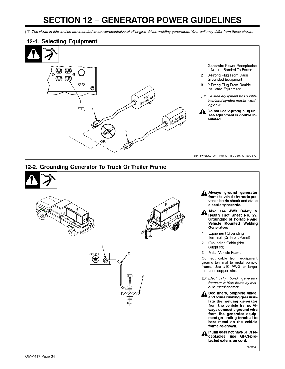
12-1. Selecting Equipment
1
2
3
OR
1Generator Power Receptacles − Neutral Bonded To Frame
2
3
.Be sure equipment has double
insulated symbol and/or word- ing on it.
Do not use
gen_pwr 2007−04 − Ref.
12-2. Grounding Generator To Truck Or Trailer Frame
1
GND/PE2
3
Always ground generator frame to vehicle frame to pre- vent electric shock and static electricity hazards.
Also see AWS Safety & Health Fact Sheet No. 29, Grounding of Portable And Vehicle Mounted Welding Generators.
1Equipment Grounding Terminal (On Front Panel)
2Grounding Cable (Not Supplied)
3Metal Vehicle Frame
Connect cable from equipment ground terminal to metal vehicle frame. Use #10 AWG or larger insulated copper wire.
.Electrically bond generator frame to vehicle frame by met-
Bed liners, shipping skids, and some running gear insu- late the welding generator from the vehicle frame. Al- ways connect a ground wire from the generator equip- ment grounding terminal to bare metal on the vehicle frame as shown.
If unit does not have GFCI re- ceptacles, use