Visit our website at
www.MillerWelds.com
OM-4417 210 403F
2007−05
Processes
Stick (SMAW) Welding
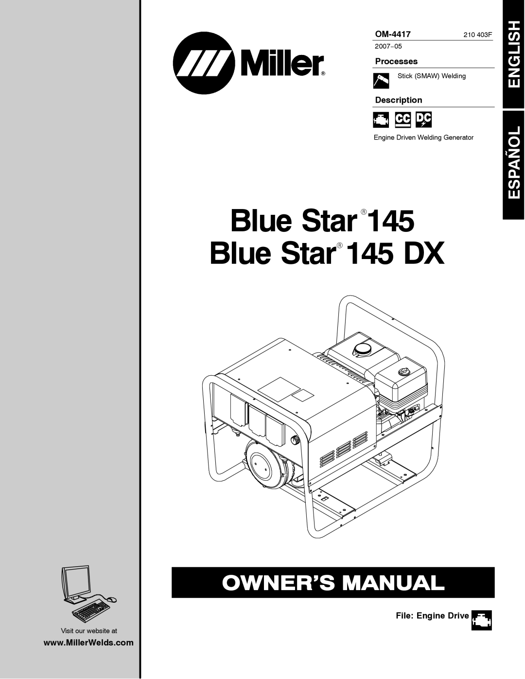
Description
Engine Driven Welding Generator
Blue StarR145 Blue StarR 145 DX
File: Engine Drive 
ENGLISH
ESPAÑOL
Visit our website at
www.MillerWelds.com
2007−05
Stick (SMAW) Welding
Engine Driven Welding Generator
Blue StarR145 Blue StarR 145 DX
ENGLISH
ESPAÑOL