SECTION 4 − INSTALLATION
4-1. Specifications
Wire Diameter | Approximate | Cooling | Maximum | Weld |
| Overall |
| |
Wire Feed | Circuit | IP Rating | Weight | |||||
Range | Method | Spool Size | Dimensions | |||||
Range | Rating |
|
| |||||
|
|
|
|
|
| |||
|
|
|
|
|
|
|
| |
|
|
|
|
|
|
| 2.9 lb | |
.025 Thru 1/16 in |
|
|
|
|
|
| (1.3 kg) Gun | |
|
|
| 100 Volts, |
| Length: | Only | ||
(0.6 Thru 1.6 mm) |
|
|
|
| ||||
|
|
| 200 Amperes, |
| (390 mm) |
| ||
Aluminum Wire | 70 To 875 ipm |
|
|
|
| |||
| 4 in (102 mm) | 100% Duty |
| Width: | 15A Model: | |||
| (1.7 To 22.2 | Air Cooled | IP 23 | |||||
| Diameter | Cycle Using | (64 mm) | 9 lb (4.1 kg) | ||||
.025 Thru .045 in | mpm) |
|
| |||||
|
| Argon |
| Height: | Gun With Cable | |||
(0.6 Thru 1.1 mm) |
|
|
|
| ||||
|
|
| Shielding Gas |
| (273 mm) | 30A Model: | ||
Hard Or Cored Wire |
|
|
|
| ||||
|
|
|
|
|
| 14 lb (6.4 kg) | ||
|
|
|
|
|
|
| ||
|
|
|
|
|
|
| Gun With Cable | |
|
|
|
|
|
|
|
|
NOTE
Use weld control or welding power source Owner’s Manual during gun installation. If contact tip, liner, and drive roll groove are not correct for wire size and type, see Section 6 to change parts as needed. See Parts List for other available contact tips.
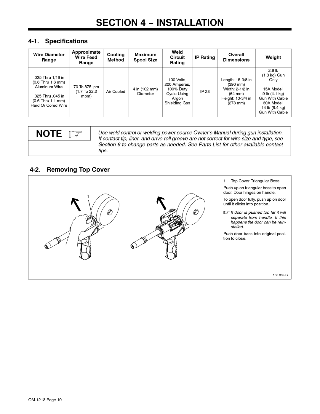
4-2. Removing Top Cover
| 1 Top Cover Triangular Boss | |
| Push up on triangular boss to open | |
1 | door. Door hinges on handle. | |
To open door fully, push up on door | ||
| ||
| until it clicks into position. | |
| . If door is pushed too far it will | |
| separate from handle. If this | |
| happens the door can be rein- | |
| stalled. | |
| Push door back into original posi- | |
| tion to close. |
150