Manuals
/
Miller Electric
/
Power Tools
/
Welder
Miller Electric
30A, 15A
manual
Electrical Diagram, Circuit Diagram For Gun/Feeder
Models:
15A
30A
1
25
36
36
Download
36 pages
23.19 Kb
22
23
24
25
26
27
28
29
Troubleshooting
Specs
Install
Electrical Diagram
Symbol Usage
Maintenance
Complete Assembly
Safety
Page 25
Image 25
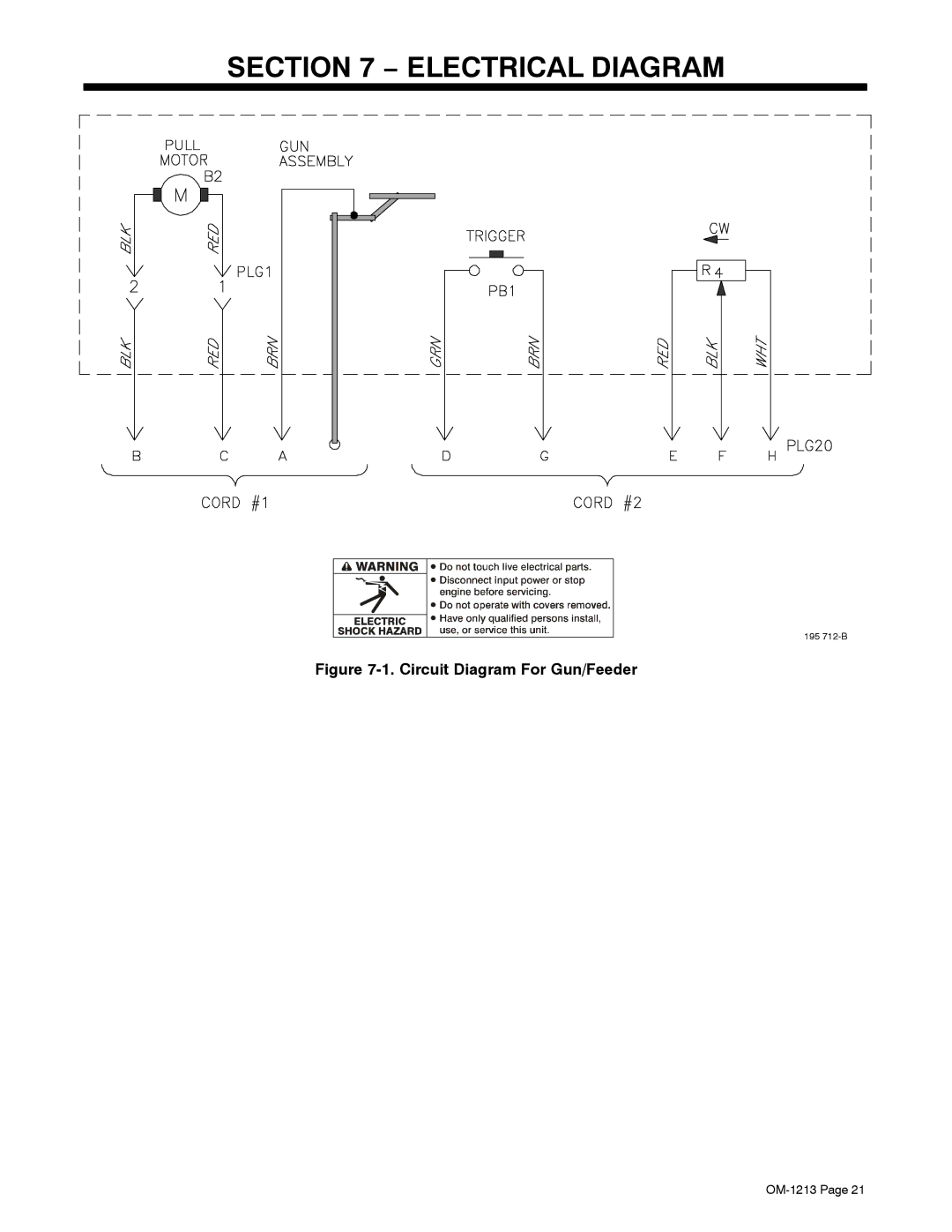
SECTION 7 − ELECTRICAL DIAGRAM
195
712-B
Figure
7-1.
Circuit Diagram For Gun/Feeder
OM-1213
Page 21
Page 24
Page 26
Page 25
Image 25
Page 24
Page 26
Contents
Description
Processes
File MIG Gmaw
From Miller to You
Table of Contents
Standards
Directives
Arc Welding Hazards
Symbol Usage
Electric Shock can kill
Fumes and Gases can be hazardous
Welding can cause fire or explosion
ARC Rays can burn eyes and skin
Flying Metal can injure eyes
Buildup of GAS can injure or kill
California Proposition 65 Warnings
EMF Information
Principal Safety Standards
LES Fumées ET LES GAZ peuvent être dangereux
UNE Décharge Électrique peut entraîner la mort
Incendie ou une explosion
LE Soudage peut provoquer un
DES Particules Volantes peuvent blesser les yeux
DES Pièces Chaudes peuvent provoquer des brûlures graves
LA Chute DE L’APPAREIL peut blesser
Risque D’INCENDIE OU D’EXPLO
’EMPLOI Excessif peut SUR
DES Organes Mobiles peuvent provoquer des blessures
Principales normes de sécurité
− Definitions
Symbols And Definitions
Manufacturer’s Rating Label For CE Products
Specifications
− Installation
Removing Top Cover
Rotating Canister
Installing Wire Spool And Threading Welding Wire
Connecting To 115 Volt Weld Control
Connecting To 24 Volt Weld Control
Installing Gas Supply
Turn On unit and check drive roll
Adjusting Drive Roll And Spool Brake Pressure
Controls
− Operation
Shielding Gas
Changing Gun Contact Tip
− Maintenance & Troubleshooting
Replacing Head Tube Liner
Gun Drive Assembly Maintenance
Replacing Spool Canister
Replacing Canister Inlet Guide
Replacing Diffuser
Troubleshooting
Circuit Diagram For Gun/Feeder
− Electrical Diagram
Complete Assembly
Quantity
Dia Part Mkgs Description Quantity
Number
− Parts List Including Consumables
Extra Heavy Duty FasTiptContact Tips
Heavy Duty FasTiptContact Tips
Tapered FasTipt Contact Tips
Insulators
Gas Diffusers
Barrel Assemblies
Head Tube Assemblies
Page
Start Your Professional Welding Career Now
Page
Call Miller for your local Miller distributor
Miller Electric Mfg. Co
Owner’s Record
Top
Page
Image
Contents