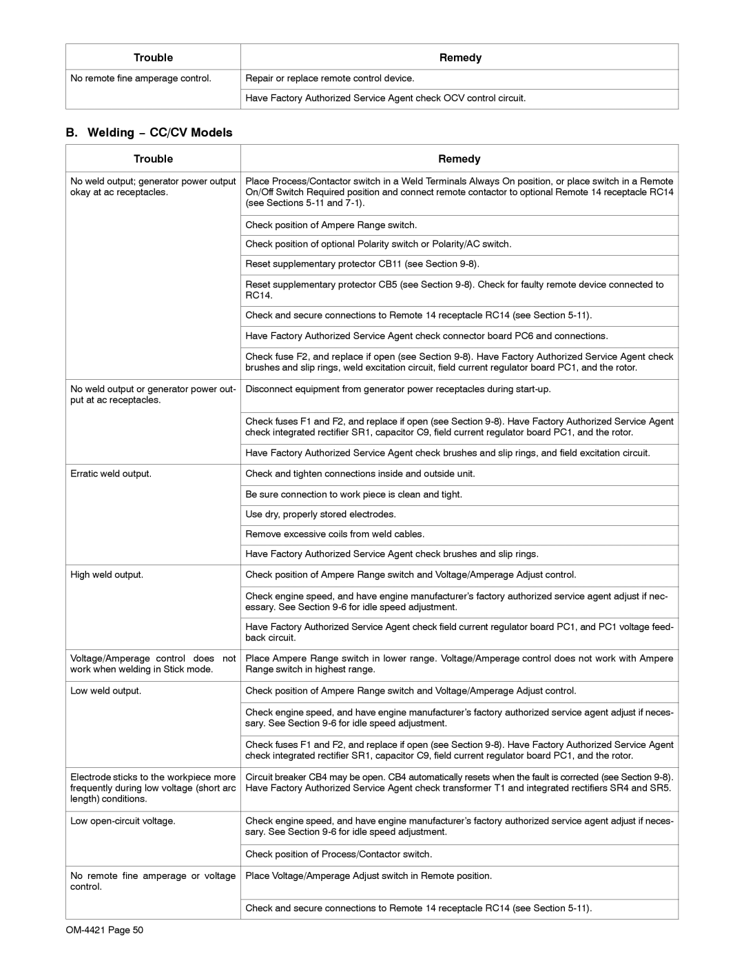
Trouble | Remedy |
|
|
No remote fine amperage control. | Repair or replace remote control device. |
|
|
| Have Factory Authorized Service Agent check OCV control circuit. |
|
|
B. Welding − CC/CV Models
Trouble | Remedy |
|
|
No weld output; generator power output | Place Process/Contactor switch in a Weld Terminals Always On position, or place switch in a Remote |
okay at ac receptacles. | On/Off Switch Required position and connect remote contactor to optional Remote 14 receptacle RC14 |
| (see Sections |
|
|
| Check position of Ampere Range switch. |
|
|
| Check position of optional Polarity switch or Polarity/AC switch. |
|
|
| Reset supplementary protector CB11 (see Section |
|
|
| Reset supplementary protector CB5 (see Section |
| RC14. |
|
|
| Check and secure connections to Remote 14 receptacle RC14 (see Section |
|
|
| Have Factory Authorized Service Agent check connector board PC6 and connections. |
|
|
| Check fuse F2, and replace if open (see Section |
| brushes and slip rings, weld excitation circuit, field current regulator board PC1, and the rotor. |
|
|
No weld output or generator power out- | Disconnect equipment from generator power receptacles during |
put at ac receptacles. |
|
|
|
| Check fuses F1 and F2, and replace if open (see Section |
| check integrated rectifier SR1, capacitor C9, field current regulator board PC1, and the rotor. |
|
|
| Have Factory Authorized Service Agent check brushes and slip rings, and field excitation circuit. |
|
|
Erratic weld output. | Check and tighten connections inside and outside unit. |
|
|
| Be sure connection to work piece is clean and tight. |
|
|
| Use dry, properly stored electrodes. |
|
|
| Remove excessive coils from weld cables. |
|
|
| Have Factory Authorized Service Agent check brushes and slip rings. |
|
|
High weld output. | Check position of Ampere Range switch and Voltage/Amperage Adjust control. |
|
|
| Check engine speed, and have engine manufacturer’s factory authorized service agent adjust if nec- |
| essary. See Section |
|
|
| Have Factory Authorized Service Agent check field current regulator board PC1, and PC1 voltage feed- |
| back circuit. |
|
|
Voltage/Amperage control does not | Place Ampere Range switch in lower range. Voltage/Amperage control does not work with Ampere |
work when welding in Stick mode. | Range switch in highest range. |
|
|
Low weld output. | Check position of Ampere Range switch and Voltage/Amperage Adjust control. |
|
|
| Check engine speed, and have engine manufacturer’s factory authorized service agent adjust if neces- |
| sary. See Section |
|
|
| Check fuses F1 and F2, and replace if open (see Section |
| check integrated rectifier SR1, capacitor C9, field current regulator board PC1, and the rotor. |
|
|
Electrode sticks to the workpiece more | Circuit breaker CB4 may be open. CB4 automatically resets when the fault is corrected (see Section |
frequently during low voltage (short arc | Have Factory Authorized Service Agent check transformer T1 and integrated rectifiers SR4 and SR5. |
length) conditions. |
|
|
|
Low | Check engine speed, and have engine manufacturer’s factory authorized service agent adjust if neces- |
| sary. See Section |
|
|
| Check position of Process/Contactor switch. |
|
|
No remote fine amperage or voltage | Place Voltage/Amperage Adjust switch in Remote position. |
control. |
|
|
|
| Check and secure connections to Remote 14 receptacle RC14 (see Section |
|
|
