SECTION 4 − OPERATION
4-1. Controls
|
|
|
|
|
|
|
|
|
|
|
|
|
|
|
|
|
|
|
|
|
|
|
|
|
|
|
|
|
|
|
|
|
|
|
|
|
|
|
|
|
|
|
|
|
|
|
|
|
|
|
|
|
|
|
|
|
|
|
|
|
|
|
|
|
|
|
|
|
|
|
|
|
|
|
|
|
|
|
|
|
|
|
|
|
|
|
|
|
|
|
|
|
|
|
|
2 | 5 | 3 | 4 | ||||||||||||
|
|
|
|
|
|
|
|
|
|
|
|
|
|
|
|
|
|
|
|
|
|
|
|
|
|
|
|
|
|
|
|
|
|
|
|
|
|
|
|
|
|
|
|
|
|
|
|
1
6
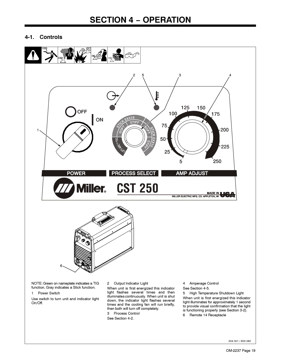
NOTE: Green on nameplate indicates a TIG function, Gray indicates a Stick function.
1 Power Switch
Use switch to turn unit and indicator light On/Off.
2 Output Indicator Light
When unit is first energized this indicator light flashes several times and then illuminates continuously. When unit is shut down, the indicator light flashes several times and the cooling fan will run briefly, then both will turn off completely.
3Process Control See Section
4Amperage Control See Section
5High Temperature Shutdown Light
When unit is first energized this indicator light illuminates for approximately 1 second to provide visual confirmation that the light is functioning properly (see Section
6 Remote 14 Receptacle
204 301 / 803 080
