. Hardware is common and
not available unless listed. | 11 |
| |
| 12 |
| 13 |
7
6
| 2 |
9 | 3 |
|
5
10
12
13
4
8
1
|
|
|
| 803 |
|
|
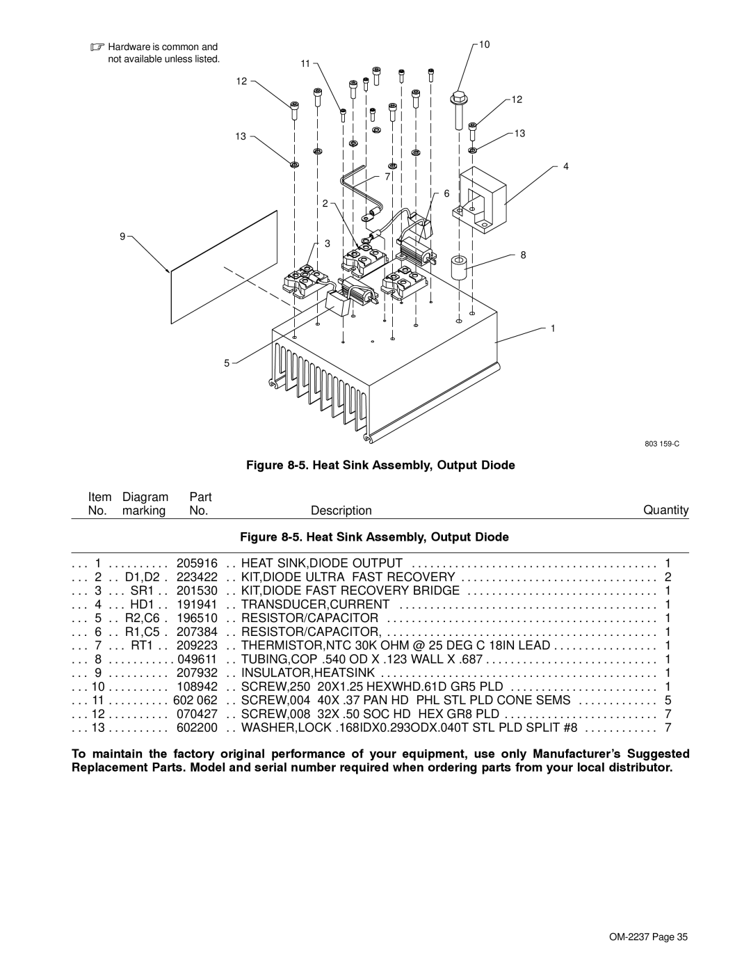
| Figure |
|
Item | Diagram | Part |
| Quantity |
No. | marking | No. | Description | |
|
|
| Figure |
|
|
|
|
|
|
. . . 1 . . | . . . . . . . . | 205916 | . . HEAT SINK,DIODE OUTPUT | . . . 1 |
. . . 2 . . D1,D2 . | 223422 | . . KIT,DIODE ULTRA−FAST RECOVERY | . . . 2 | |
. . . 3 . . . SR1 . . | 201530 | . . KIT,DIODE FAST RECOVERY BRIDGE | . . . 1 | |
. . . 4 . . . HD1 . . | 191941 | . . TRANSDUCER,CURRENT | . . . 1 | |
. . . 5 . . R2,C6 . | 196510 | . . RESISTOR/CAPACITOR | . . . 1 | |
. . . 6 . . R1,C5 . | 207384 | . . RESISTOR/CAPACITOR, . . . . . . . . . . . . . . . . . . . . . . . . . . . . . . . . . . . . . . . . . . . . 1 | ||
. . . 7 . . . RT1 . . | 209223 | . . THERMISTOR,NTC 30K OHM @ 25 DEG C 18IN LEAD | . . . 1 | |
. . . 8 . . | . . . . . . . . | . 049611 | . . TUBING,COP .540 OD X .123 WALL X .687 | . . . 1 |
. . . 9 . . | . . . . . . . . | 207932 | . . INSULATOR,HEATSINK | . . . 1 |
. . . 10 . . | . . . . . . . . | 108942 | . . SCREW,250−20X1.25 HEXWHD.61D GR5 PLD | . . . 1 |
. . . 11 . . | . . . . . . . . | 602 062 | . . SCREW,004−40X .37 PAN HD−PHL STL PLD CONE SEMS | . . . 5 |
. . . 12 . . | . . . . . . . . | 070427 | . . SCREW,008−32X .50 SOC HD−HEX GR8 PLD | . . . 7 |
. . . 13 . . | . . . . . . . . | 602200 | . . WASHER,LOCK .168IDX0.293ODX.040T STL PLD SPLIT #8 | . . . 7 |
To maintain the factory original performance of your equipment, use only Manufacturer’s Suggested Replacement Parts. Model and serial number required when ordering parts from your local distributor.
