3-11. Selecting 460 - 575 Volts AC Three Phase Input Voltage
3 Top Cover Securing
Screws — Left And
Right Side Panel
2 Top Cover Securing
Screws — Front And
Rear Panel
1 ![]()
![]()
2 3
5
43
Tools Needed:
5/16 in
YTurn Off welding power source, and disconnect
input power before proceeding.
Check input voltage available at site.
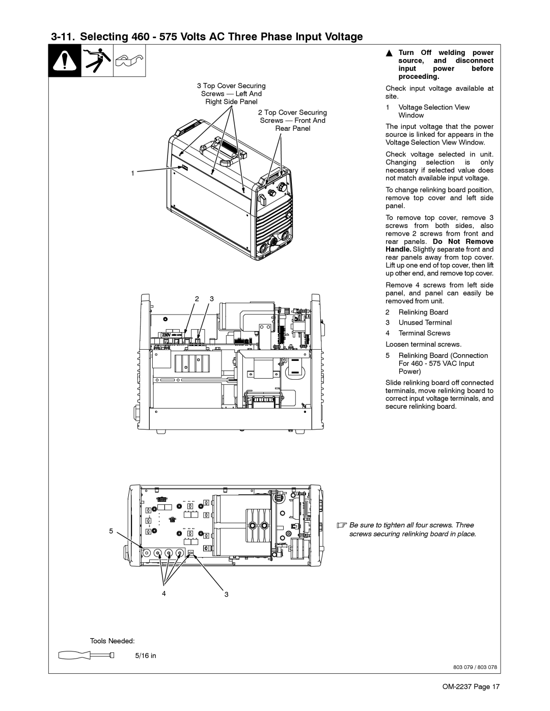
1Voltage Selection View Window
The input voltage that the power source is linked for appears in the Voltage Selection View Window.
Check voltage selected in unit. Changing selection is only necessary if selected value does not match available input voltage.
To change relinking board position, remove top cover and left side panel.
To remove top cover, remove 3 screws from both sides, also remove 2 screws from front and rear panels. Do Not Remove Handle. Slightly separate front and rear panels away from top cover. Lift up one end of top cover, then lift up other end, and remove top cover.
Remove 4 screws from left side panel, and panel can easily be removed from unit.
2Relinking Board
3Unused Terminal
4Terminal Screws Loosen terminal screws.
5Relinking Board (Connection For 460 - 575 VAC Input Power)
Slide relinking board off connected terminals, move relinking board to correct input voltage terminals, and secure relinking board.
.Be sure to tighten all four screws. Three screws securing relinking board in place.
803 079 / 803 078
