3-12. Connecting Input Power
Green Or
Green/Yellow
3 | 1 |
|
2 |
| |
L1 |
| |
L2 | L1 | |
L3 | ||
L2 | ||
|
Green Or
Green/Yellow
YAlways connect grounding conductor first
=GND/PE 1
1
Green or
Green/Yellow
6 ![]()
1
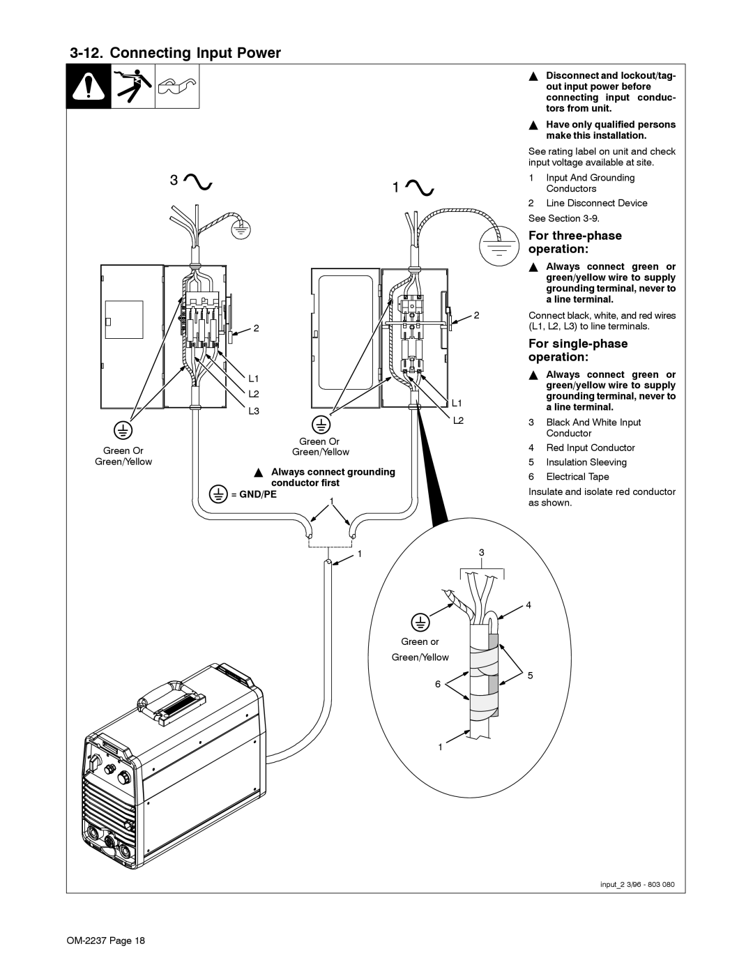
YDisconnect and lockout/tag- out input power before connecting input conduc- tors from unit.
YHave only qualified persons make this installation.
See rating label on unit and check input voltage available at site.
1Input And Grounding Conductors
2Line Disconnect Device See Section
For three-phase operation:
YAlways connect green or green/yellow wire to supply grounding terminal, never to a line terminal.
2Connect black, white, and red wires (L1, L2, L3) to line terminals.
For single-phase operation:
YAlways connect green or green/yellow wire to supply grounding terminal, never to a line terminal.
3Black And White Input Conductor
4Red Input Conductor
5Insulation Sleeving
6Electrical Tape
Insulate and isolate red conductor as shown.
3
4
![]() 5
5
input_2 3/96 - 803 080