Item | Dia. | Part | Description | Quantity | |
| No. | Mkgs. | No. | ||
|
|
|
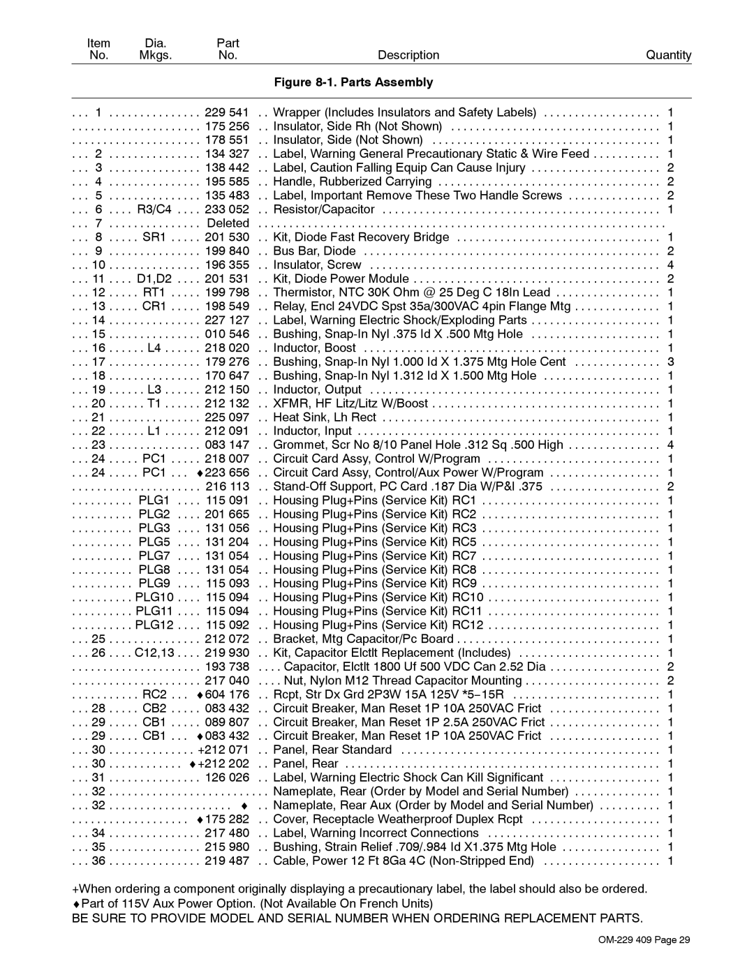
| Figure |
|
|
|
|
|
|
|
. . . | 1 . . . . | . . . . . . . | . . . . 229 541 | . . Wrapper (Includes Insulators and Safety Labels) | . . . 1 |
. . . | . . . . . . . | . . . . . . . | . . . . 175 256 | . . Insulator, Side Rh (Not Shown) | . . . 1 |
. . . | . . . . . . . | . . . . . . . | . . . . 178 551 | . . Insulator, Side (Not Shown) | . . . 1 |
. . . | 2 . . . . | . . . . . . . | . . . . 134 327 | . . Label, Warning General Precautionary Static & Wire Feed | . . . 1 |
. . . | 3 . . . . | . . . . . . . | . . . . 138 442 | . . Label, Caution Falling Equip Can Cause Injury | . . . 2 |
. . . | 4 . . . . | . . . . . . . | . . . . 195 585 | . . Handle, Rubberized Carrying | . . . 2 |
. . . | 5 . . . . | . . . . . . . | . . . . 135 483 | . . Label, Important Remove These Two Handle Screws | . . . 2 |
. . . 6 . . . . R3/C4 | . . . . 233 052 | . . Resistor/Capacitor | . . . 1 | ||
. . . | 7 . . . . | . . . . . . . | . . . . Deleted | . . . . . . . . . . . . . . . . . . . . . . . . . . . . . . . . . . . . . . . . . . . . . . . . . . . . . . . . . . . . . . | . . . . |
. . . 8 . . . . . SR1 . | . . . . 201 530 | . . Kit, Diode Fast Recovery Bridge | . . . 1 | ||
. . . | 9 . . . . | . . . . . . . | . . . . 199 840 | . . Bus Bar, Diode | . . . 2 |
. . . 10 . . . . | . . . . . . . | . . . . 196 355 | . . Insulator, Screw | . . . 4 | |
. . . 11 . . . . | D1,D2 | . . . . 201 531 | . . Kit, Diode Power Module | . . . 2 | |
. . . 12 . . . . | . RT1 . | . . . . 199 798 | . . Thermistor, NTC 30K Ohm @ 25 Deg C 18In Lead | . . . 1 | |
. . . 13 . . . . | . CR1 . | . . . . 198 549 | . . Relay, Encl 24VDC Spst 35a/300VAC 4pin Flange Mtg | . . . 1 | |
. . . 14 . . . . | . . . . . . . | . . . . 227 127 | . . Label, Warning Electric Shock/Exploding Parts | . . . 1 | |
. . . 15 . . . . | . . . . . . . | . . . . 010 546 | . . Bushing, | . . . 1 | |
. . . 16 . . . . | . . L4 . . | . . . . 218 020 | . . Inductor, Boost | . . . 1 | |
. . . 17 . . . . | . . . . . . . | . . . . 179 276 | . . Bushing, | . . . 3 | |
. . . 18 . . . . | . . . . . . . | . . . . 170 647 | . . Bushing, | . . . 1 | |
. . . 19 . . . . | . . L3 . . | . . . . 212 150 | . . Inductor, Output | . . . 1 | |
. . . 20 . . . . | . . T1 . . | . . . . 212 132 | . . XFMR, HF Litz/Litz W/Boost | . . . 1 | |
. . . 21 . . . . | . . . . . . . | . . . . 225 097 | . . Heat Sink, Lh Rect | . . . 1 | |
. . . 22 . . . . | . . L1 . . | . . . . 212 091 | . . Inductor, Input | . . . 1 | |
. . . 23 . . . . | . . . . . . . | . . . . 083 147 | . . Grommet, Scr No 8/10 Panel Hole .312 Sq .500 High | . . . 4 | |
. . . 24 . . . . | . PC1 . | . . . . 218 007 | . . Circuit Card Assy, Control W/Program | . . . 1 | |
. . . 24 . . . . | . PC1 . | . . ♦223 656 | . . Circuit Card Assy, Control/Aux Power W/Program | . . . 1 | |
. . . | . . . . . . . | . . . . . . . | . . . . 216 113 | . . | . . . 2 |
. . . | . . . . . . . | PLG1 | . . . . 115 091 | . . Housing Plug+Pins (Service Kit) RC1 | . . . 1 |
. . . | . . . . . . . | PLG2 | . . . . 201 665 | . . Housing Plug+Pins (Service Kit) RC2 | . . . 1 |
. . . | . . . . . . . | PLG3 | . . . . 131 056 | . . Housing Plug+Pins (Service Kit) RC3 | . . . 1 |
. . . | . . . . . . . | PLG5 | . . . . 131 204 | . . Housing Plug+Pins (Service Kit) RC5 | . . . 1 |
. . . | . . . . . . . | PLG7 | . . . . 131 054 | . . Housing Plug+Pins (Service Kit) RC7 | . . . 1 |
. . . | . . . . . . . | PLG8 | . . . . 131 054 | . . Housing Plug+Pins (Service Kit) RC8 | . . . 1 |
. . . | . . . . . . . | PLG9 | . . . . 115 093 | . . Housing Plug+Pins (Service Kit) RC9 | . . . 1 |
. . . | . . . . . . . | PLG10 | . . . . 115 094 | . . Housing Plug+Pins (Service Kit) RC10 | . . . 1 |
. . . | . . . . . . . | PLG11 | . . . . 115 094 | . . Housing Plug+Pins (Service Kit) RC11 | . . . 1 |
. . . | . . . . . . . | PLG12 | . . . . 115 092 | . . Housing Plug+Pins (Service Kit) RC12 | . . . 1 |
. . . 25 . . . . | . . . . . . . | . . . . 212 072 | . . Bracket, Mtg Capacitor/Pc Board | . . . 1 | |
. . . 26 . . . . | C12,13 | . . . . 219 930 | . . Kit, Capacitor Elctlt Replacement (Includes) | . . . 1 | |
. . . | . . . . . . . | . . . . . . . | . . . . 193 738 | . . . . Capacitor, Elctlt 1800 Uf 500 VDC Can 2.52 Dia | . . . 2 |
. . . | . . . . . . . | . . . . . . . | . . . . 217 040 | . . . . Nut, Nylon M12 Thread Capacitor Mounting | . . . 2 |
. . . | . . . . . . . | . RC2 . | . . ♦604 176 | . . Rcpt, Str Dx Grd 2P3W 15A 125V *5−15R | . . . 1 |
. . . 28 . . . . | . CB2 . | . . . . 083 432 | . . Circuit Breaker, Man Reset 1P 10A 250VAC Frict | . . . 1 | |
. . . 29 . . . . | . CB1 . | . . . . 089 807 | . . Circuit Breaker, Man Reset 1P 2.5A 250VAC Frict | . . . 1 | |
. . . 29 . . . . | . CB1 . | . . ♦083 432 | . . Circuit Breaker, Man Reset 1P 10A 250VAC Frict | . . . 1 | |
. . . 30 . . . . | . . . . . . . | . . . +212 071 | . . Panel, Rear Standard | . . . 1 | |
. . . 30 . . . . | . . . . . . . | . ♦+212 202 | . . Panel, Rear | . . . 1 | |
. . . 31 . . . . | . . . . . . . | . . . . 126 026 | . . Label, Warning Electric Shock Can Kill Significant | . . . 1 | |
. . . 32 . . . . | . . . . . . . | .. .. .. .. .. .. .. .. .. . .♦. . | . . Nameplate, Rear (Order by Model and Serial Number) | . . . 1 | |
. . . 32 . . . . | . . . . . . . | . . Nameplate, Rear Aux (Order by Model and Serial Number) | . . . 1 | ||
. . . | . . . . . . . | . . . . . . . | . . ♦175 282 | . . Cover, Receptacle Weatherproof Duplex Rcpt | . . . 1 |
. . . 34 . . . . | . . . . . . . | . . . . 217 480 | . . Label, Warning Incorrect Connections | . . . 1 | |
. . . 35 . . . . | . . . . . . . | . . . . 215 980 | . . Bushing, Strain Relief .709/.984 Id X1.375 Mtg Hole | . . . 1 | |
. . . 36 . . . . | . . . . . . . | . . . . 219 487 | . . Cable, Power 12 Ft 8Ga 4C | . . . 1 | |
+When ordering a component originally displaying a precautionary label, the label should also be ordered. ♦Part of 115V Aux Power Option. (Not Available On French Units)
BE SURE TO PROVIDE MODEL AND SERIAL NUMBER WHEN ORDERING REPLACEMENT PARTS.