Interconnecting

Cord

Positive

Output

Terminal

Positive Lead

Negative Lead

(No. 17)

(No. 12)


Negative

Output

Terminal

ST-059 589-A

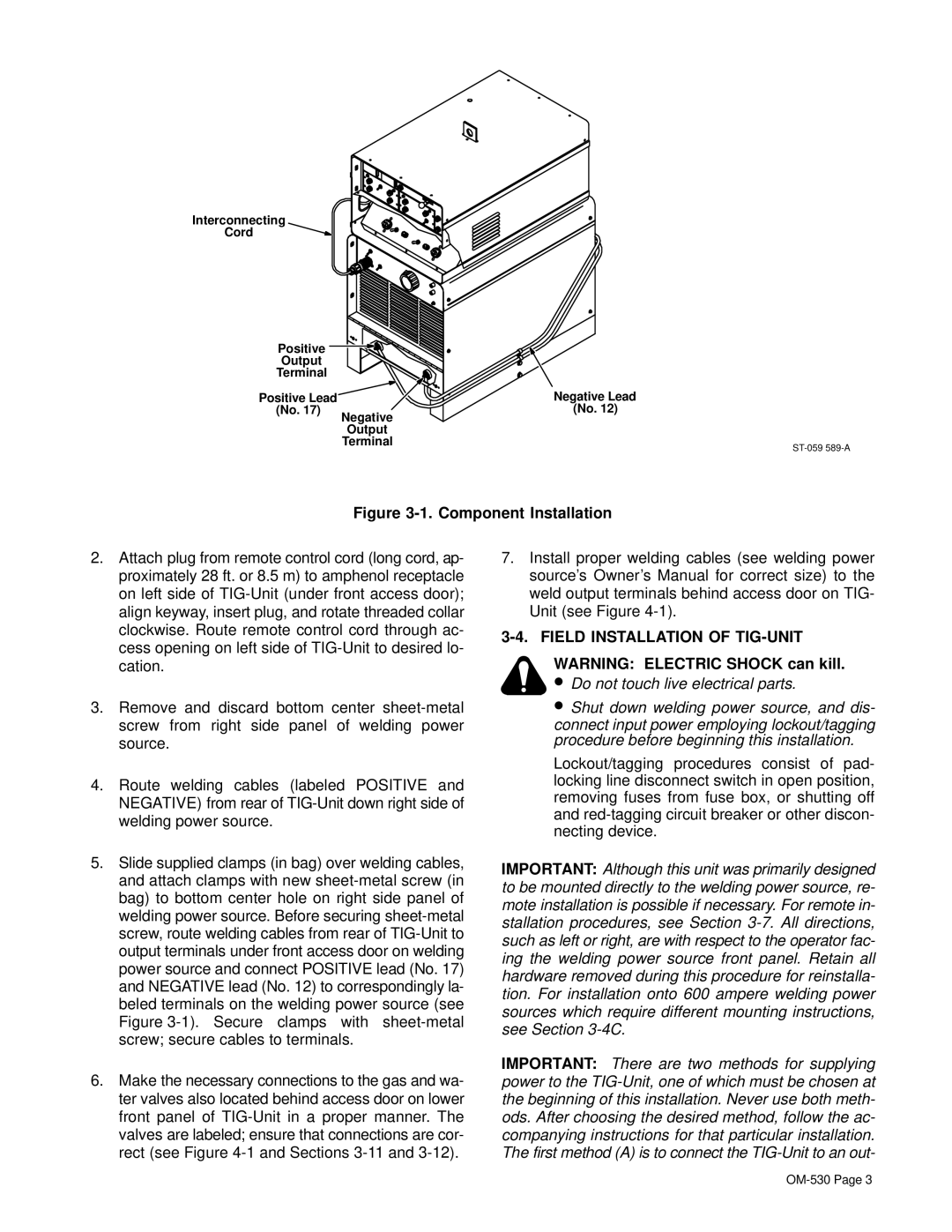
Figure 3-1. Component Installation

2.Attach plug from remote control cord (long cord, ap- proximately 28 ft. or 8.5 m) to amphenol receptacle on left side of TIG-Unit (under front access door); align keyway, insert plug, and rotate threaded collar clockwise. Route remote control cord through ac- cess opening on left side of TIG-Unit to desired lo- cation.

3.Remove and discard bottom center sheet-metal screw from right side panel of welding power source.

4.Route welding cables (labeled POSITIVE and NEGATIVE) from rear of TIG-Unit down right side of welding power source.

5.Slide supplied clamps (in bag) over welding cables, and attach clamps with new sheet-metal screw (in bag) to bottom center hole on right side panel of welding power source. Before securing sheet-metal screw, route welding cables from rear of TIG-Unit to output terminals under front access door on welding power source and connect POSITIVE lead (No. 17) and NEGATIVE lead (No. 12) to correspondingly la- beled terminals on the welding power source (see Figure 3-1). Secure clamps with sheet-metal screw; secure cables to terminals.

6.Make the necessary connections to the gas and wa- ter valves also located behind access door on lower front panel of TIG-Unit in a proper manner. The valves are labeled; ensure that connections are cor- rect (see Figure 4-1 and Sections 3-11 and 3-12).

7.Install proper welding cables (see welding power source’s Owner’s Manual for correct size) to the weld output terminals behind access door on TIG- Unit (see Figure 4-1).

3-4. FIELD INSTALLATION OF TIG-UNIT

WARNING: ELECTRIC SHOCK can kill.

Do not touch live electrical parts.

Shut down welding power source, and dis- connect input power employing lockout/tagging procedure before beginning this installation.

Lockout/tagging procedures consist of pad- locking line disconnect switch in open position, removing fuses from fuse box, or shutting off and red-tagging circuit breaker or other discon- necting device.

IMPORTANT: Although this unit was primarily designed to be mounted directly to the welding power source, re- mote installation is possible if necessary. For remote in- stallation procedures, see Section 3-7. All directions, such as left or right, are with respect to the operator fac- ing the welding power source front panel. Retain all hardware removed during this procedure for reinstalla- tion. For installation onto 600 ampere welding power sources which require different mounting instructions, see Section 3-4C.

IMPORTANT: There are two methods for supplying power to the TIG-Unit, one of which must be chosen at the beginning of this installation. Never use both meth- ods. After choosing the desired method, follow the ac- companying instructions for that particular installation. The first method (A) is to connect the TIG-Unit to an out-

OM-530 Page 3

Page 7
Image 7
Miller Electric KC237900 manual Component Installation, Field Installation of TIG-UNIT

KC237900 specifications

The Miller Electric KC237900 is a standout model in the realm of welding technology, specifically designed for versatility and efficiency. This machine embodies Miller's commitment to innovation and quality, making it a popular choice among professionals and hobbyists alike.

One of the main features of the KC237900 is its advanced inverter technology, which allows the unit to operate efficiently across a range of welding applications. This technology ensures that the welder maintains a stable arc for precision welding, even on thin materials. The inverter design also contributes to a lighter and more compact machine, enhancing portability without compromising on power.

The KC237900 supports multiple welding processes, including MIG, Flux-Cored, and Stick welding. This versatility makes it suitable for a variety of projects, from automotive repairs to intricate fabrication tasks. The machine’s ability to handle diverse materials, including steel, stainless steel, and aluminum, further expands its application scope.

Another characteristic of the Miller Electric KC237900 is its user-friendly interface. The digital display provides clear information on amperage and voltage settings, allowing welders to make quick adjustments as needed. Additionally, the intuitive control panel simplifies the operation, making it accessible to users with varying skill levels.

The arc technology integrated into the KC237900 contributes to its smooth and stable welding performance. The unit utilizes Miller's Auto-Set feature, which automatically adjusts parameters based on material thickness and type. This feature not only speeds up the setup process but also enhances the overall weld quality.

Durability is another key aspect of the KC237900. Built with robust materials, the machine is designed to withstand the rigors of job site conditions. Its protective features, such as thermal overload protection, ensure that the unit operates safely and efficiently.

In conclusion, the Miller Electric KC237900 is a high-performance welding machine that combines advanced inverter technology, versatility, and user-friendly features. With its ability to handle multiple welding processes and materials, along with its focus on reliability and ease of use, it stands out as an excellent choice for both experienced welders and newcomers to the trade. Whether for professional use or personal projects, the KC237900 delivers the performance and quality that Miller Electric is known for.