f.Cut off and discard existing connectors on Elec- troslope leads 58 and 59.

CAUTION: SOLDER can damage unit.

Do not allow solder to fall into unit.

Cover exposed area of unit when soldering connections.

Remove cover(s) and clean unit when fin- ished soldering.

g.Splice and solder Electroslope lead 59 to lead

59.(Make connection near Preflow Circuit Board.) Insulate connection with tape.

h.Connect lead 58, originating at Preflow Circuit Board, to terminal 4 of relay CR2.

i.Splice and solder Electroslope lead 58 to lead

58.(Make connection near terminal 4 of relay CR2.) Insulate connection with tape.

10.Secure leads to existing harness with nylon cable ties or tape to maintain a proper lead dress.

11.Reinstall cover onto TIG-Unit.

Terminal

Lifting

Front Center

Front Of

Strips

Eye

Mounting Panel

Tig-Unit

1T


Relay CR2


Primary Connection

Lead 60 From

Terminal

Terminal Strip TE1

Electroslope

Strip 2T


TOP VIEW

ST-081 854-C

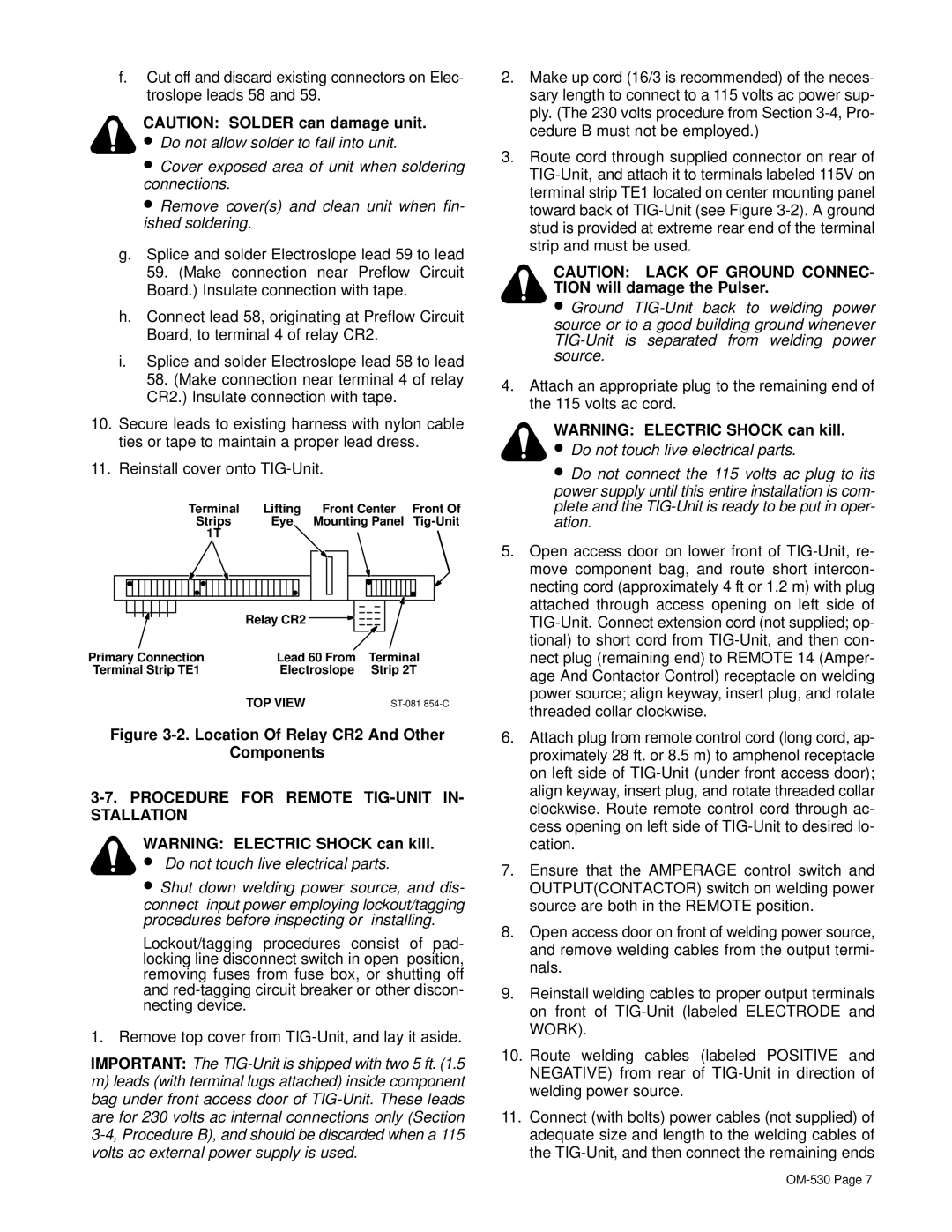
Figure 3-2. Location Of Relay CR2 And Other

Components

3-7. PROCEDURE FOR REMOTE TIG-UNIT IN- STALLATION

WARNING: ELECTRIC SHOCK can kill.

Do not touch live electrical parts.

Shut down welding power source, and dis- connect input power employing lockout/tagging procedures before inspecting or installing.

Lockout/tagging procedures consist of pad- locking line disconnect switch in open position, removing fuses from fuse box, or shutting off and red-tagging circuit breaker or other discon- necting device.

1. Remove top cover from TIG-Unit, and lay it aside.

IMPORTANT: The TIG-Unit is shipped with two 5 ft. (1.5

m)leads (with terminal lugs attached) inside component bag under front access door of TIG-Unit. These leads are for 230 volts ac internal connections only (Section 3-4, Procedure B), and should be discarded when a 115 volts ac external power supply is used.

2.Make up cord (16/3 is recommended) of the neces- sary length to connect to a 115 volts ac power sup- ply. (The 230 volts procedure from Section 3-4, Pro- cedure B must not be employed.)

3.Route cord through supplied connector on rear of TIG-Unit, and attach it to terminals labeled 115V on terminal strip TE1 located on center mounting panel toward back of TIG-Unit (see Figure 3-2). A ground stud is provided at extreme rear end of the terminal strip and must be used.

CAUTION: LACK OF GROUND CONNEC- TION will damage the Pulser.

Ground TIG-Unit back to welding power source or to a good building ground whenever TIG-Unit is separated from welding power source.

4.Attach an appropriate plug to the remaining end of the 115 volts ac cord.

WARNING: ELECTRIC SHOCK can kill.

Do not touch live electrical parts.

Do not connect the 115 volts ac plug to its power supply until this entire installation is com- plete and the TIG-Unit is ready to be put in oper- ation.

5.Open access door on lower front of TIG-Unit, re- move component bag, and route short intercon- necting cord (approximately 4 ft or 1.2 m) with plug attached through access opening on left side of TIG-Unit. Connect extension cord (not supplied; op- tional) to short cord from TIG-Unit, and then con- nect plug (remaining end) to REMOTE 14 (Amper- age And Contactor Control) receptacle on welding power source; align keyway, insert plug, and rotate threaded collar clockwise.

6.Attach plug from remote control cord (long cord, ap- proximately 28 ft. or 8.5 m) to amphenol receptacle on left side of TIG-Unit (under front access door); align keyway, insert plug, and rotate threaded collar clockwise. Route remote control cord through ac- cess opening on left side of TIG-Unit to desired lo- cation.

7.Ensure that the AMPERAGE control switch and OUTPUT(CONTACTOR) switch on welding power source are both in the REMOTE position.

8.Open access door on front of welding power source, and remove welding cables from the output termi- nals.

9.Reinstall welding cables to proper output terminals on front of TIG-Unit (labeled ELECTRODE and WORK).

10.Route welding cables (labeled POSITIVE and NEGATIVE) from rear of TIG-Unit in direction of welding power source.

11.Connect (with bolts) power cables (not supplied) of adequate size and length to the welding cables of the TIG-Unit, and then connect the remaining ends

OM-530 Page 7

Page 11
Image 11
Miller Electric KC237900 manual Location Of Relay CR2 And Other Components, Procedure for Remote TIG-UNIT IN- Stallation

KC237900 specifications

The Miller Electric KC237900 is a standout model in the realm of welding technology, specifically designed for versatility and efficiency. This machine embodies Miller's commitment to innovation and quality, making it a popular choice among professionals and hobbyists alike.

One of the main features of the KC237900 is its advanced inverter technology, which allows the unit to operate efficiently across a range of welding applications. This technology ensures that the welder maintains a stable arc for precision welding, even on thin materials. The inverter design also contributes to a lighter and more compact machine, enhancing portability without compromising on power.

The KC237900 supports multiple welding processes, including MIG, Flux-Cored, and Stick welding. This versatility makes it suitable for a variety of projects, from automotive repairs to intricate fabrication tasks. The machine’s ability to handle diverse materials, including steel, stainless steel, and aluminum, further expands its application scope.

Another characteristic of the Miller Electric KC237900 is its user-friendly interface. The digital display provides clear information on amperage and voltage settings, allowing welders to make quick adjustments as needed. Additionally, the intuitive control panel simplifies the operation, making it accessible to users with varying skill levels.

The arc technology integrated into the KC237900 contributes to its smooth and stable welding performance. The unit utilizes Miller's Auto-Set feature, which automatically adjusts parameters based on material thickness and type. This feature not only speeds up the setup process but also enhances the overall weld quality.

Durability is another key aspect of the KC237900. Built with robust materials, the machine is designed to withstand the rigors of job site conditions. Its protective features, such as thermal overload protection, ensure that the unit operates safely and efficiently.

In conclusion, the Miller Electric KC237900 is a high-performance welding machine that combines advanced inverter technology, versatility, and user-friendly features. With its ability to handle multiple welding processes and materials, along with its focus on reliability and ease of use, it stands out as an excellent choice for both experienced welders and newcomers to the trade. Whether for professional use or personal projects, the KC237900 delivers the performance and quality that Miller Electric is known for.