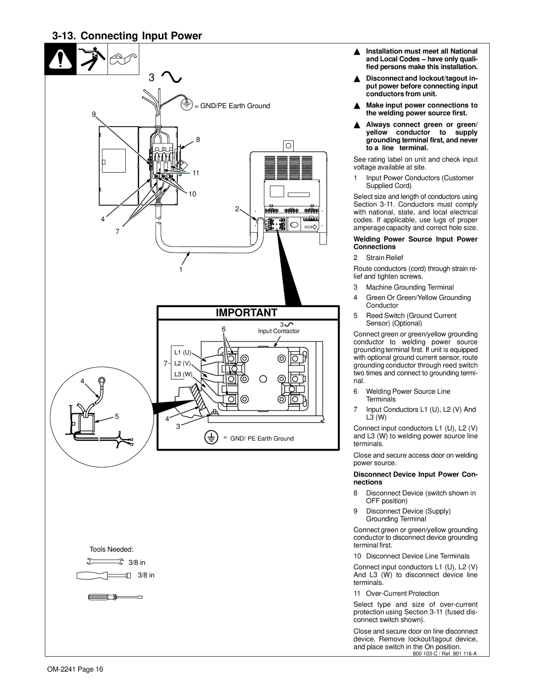
3-13. Connecting Input Power


3


= GND/PE Earth Ground

9


8


11


10


2

4


7


1


IMPORTANT


6

3


Input Contactor


L1 (U)


7

L2 (V)


4


L3 (W)


5

4


3


= GND/ PE Earth Ground

Tools Needed:

3/8 in

3/8 in

YInstallation must meet all National and Local Codes − have only quali- fied persons make this installation.

YDisconnect and lockout/tagout in- put power before connecting input conductors from unit.

YMake input power connections to the welding power source first.

YAlways connect green or green/ yellow conductor to supply grounding terminal first, and never to a line terminal.

See rating label on unit and check input voltage available at site.

1Input Power Conductors (Customer Supplied Cord)

Select size and length of conductors using Section 3-11.Conductors must comply with national, state, and local electrical codes. If applicable, use lugs of proper amperage capacity and correct hole size.

Welding Power Source Input Power Connections

2 Strain Relief

Route conductors (cord) through strain re- lief and tighten screws.

3Machine Grounding Terminal

4Green Or Green/Yellow Grounding Conductor

5Reed Switch (Ground Current Sensor) (Optional)

Connect green or green/yellow grounding conductor to welding power source grounding terminal first. If unit is equipped with optional ground current sensor, route grounding conductor through reed switch two times and connect to grounding termi- nal.

6Welding Power Source Line Terminals

7Input Conductors L1 (U), L2 (V) And L3 (W)

Connect input conductors L1 (U), L2 (V) and L3 (W) to welding power source line terminals.

Close and secure access door on welding power source.

Disconnect Device Input Power Con- nections

8Disconnect Device (switch shown in OFF position)

9Disconnect Device (Supply) Grounding Terminal

Connect green or green/yellow grounding conductor to disconnect device grounding terminal first.

10 Disconnect Device Line Terminals

Connect input conductors L1 (U), L2 (V) And L3 (W) to disconnect device line terminals.

11 Over-Current Protection

Select type and size of over-current protection using Section 3-11(fused dis- connect switch shown).

Close and secure door on line disconnect device. Remove lockout/tagout device, and place switch in the On position.

800 103-C / Ref. 801 116-A

OM-2241 Page 16

Page 20
Image 20
Miller Electric OM-2241 manual Connecting Input Power, Welding Power Source Input Power Connections

OM-2241 specifications

The Miller Electric OM-2241 is a versatile and innovative welding machine designed for both professional and industrial use. This power source is known for its durability, performance, and user-friendly features, making it a preferred choice for welders across various sectors.

One of the main features of the OM-2241 is its advanced multi-process capabilities. This welding machine can seamlessly switch between MIG, TIG, stick, and flux-cored welding, allowing users to tackle a wide array of projects with ease. This flexibility makes it suitable for various applications, from maintenance and repair to fabrication and construction.

The OM-2241 is equipped with Miller's Auto-Set technology, which simplifies the setup process. This feature automatically adjusts the machine's settings based on the material thickness and type, enabling users to achieve optimal weld quality without the need for extensive calibration. This is particularly beneficial for both novice and experienced welders, as it reduces the learning curve and increases efficiency.

Another notable characteristic of the OM-2241 is its lightweight and portable design. Weighing significantly less than traditional welding machines, it allows for easy transportation, making it an excellent option for on-site work. The machine also boasts an ergonomic handle and intuitive control panel, enhancing user comfort and accessibility during operation.

In terms of performance, the OM-2241 provides a stable arc and reduced spatter, resulting in clean and professional-looking welds. Its built-in digital meter provides real-time feedback on voltage and amperage, allowing welders to monitor their performance closely and make adjustments as needed.

The Miller Electric OM-2241 is also engineered with durability in mind. Constructed with high-quality materials and protective features, it can withstand challenging working environments and ensure long-lasting operation. This resilience is complemented by Miller’s reputation for reliability and customer satisfaction, providing peace of mind to users.

In conclusion, the Miller Electric OM-2241 stands out in the welding equipment market due to its multifaceted capabilities, user-friendly technologies, and robust performance characteristics. Whether in a workshop or at a job site, this welding machine delivers the versatility and reliability required for various welding applications, making it an essential tool for any welder's arsenal.